
Sizing a Power Supply for Pixel LED Strip
Size the power supply for a pixel LED strip like an engineer: watts per meter, per-pixel current, voltage drop, power injection, and the 20–30% safety margin.
The two numbers that size every pixel LED strip power supply
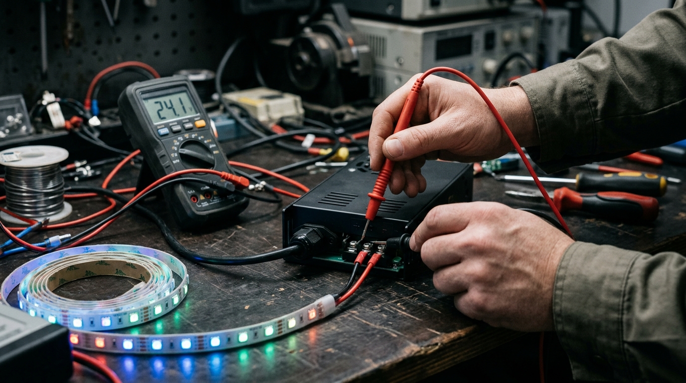
Sizing a power supply for a pixel LED strip comes down to two numbers: total worst-case wattage of the strip run, and the voltage it runs on. Multiply the strip's rated watts per meter by the length, add a 20–30% safety margin so the supply never runs at full load, and match the supply's voltage exactly to the strip. That calculation gets the wattage right — and it is where most installs stop. The part that actually fails on site is current flow: where those amps have to travel, how far they can go before voltage drops, and which supply feeds which zone.
Two common failures follow from skipping the second half. An undersized supply starves the far end of the run: pixels near the controller are bright, pixels at the end shift color or flicker, and in the worst case the supply overheats and trips. An oversized supply is the safer failure, but it still costs money and space that a project budget did not ask for. A LED strip light is a flexible PCB with SMD LEDs driven by resistors or driver ICs, and its power needs are set entirely by the chips on the PCB and the voltage you feed it. It is also one component in the wider pixel LED accessory ecosystem — the same design session that picks the supply also picks the profiles, connectors and controller, and they all have to agree on voltage and current.
The math itself is two formulas:
- Watts = Volts × Amps (W = V × A) — the load, expressed in power
- Total power (W) = strip length (m) × rated power per meter (W/m)
Example: 10 m of a 12 V strip rated 14.4 W/m draws 10 × 14.4 = 144 W at full white. Add the recommended 20–30% margin (the industry rule of thumb is to run a supply at no more than 80% of its rated capacity) and you need 144 × 1.2 ≈ 173 W — so a 200 W supply, not a 150 W. Adafruit's NeoPixel power guide uses the same approach for addressable strips: total current at full white, plus margin, and plan for injection before the voltage sags.
The margin is not optional padding. A supply run continuously at 100% runs hotter, ages faster, and trips its protection exactly when the install is at its most visible — full white on a holiday facade or a stage fill. The 20–30% headroom also absorbs the real-world gap between a datasheet figure and a reel measured warm on site.
The sizing math gets you to a number; a multimeter at full white confirms it before the strip goes into the channel.
Reading the spec sheet: watts per meter vs per-pixel current
Strip manufacturers quote power two ways, and mixing them up is where sizing errors start. The first is watts per meter (W/m) — the number printed on the product page and the one you multiply by length. The second is per-pixel current — useful when you are counting pixels, which pixel strips almost always are. Both describe the same worst case: every LED at full white.
Per-pixel current is set by the driver IC, and the IC family determines both the current and the voltage. The numbers below come from the chips' datasheets — the WS2812B datasheet defines the 20 mA per-channel limit, and the WS2811 datasheet defines the 18.5 mA constant-current outputs — and are the standard design figures used across the industry:
Driver IC | Strip voltage | Current at full white | Watts per pixel | Typical strip rating |
|---|---|---|---|---|
WS2812B | 5 V | 60 mA per pixel (3 × 20 mA channels) | 0.30 W | 60 px/m ≈ 18 W/m |
SK6812 (RGBW) | 5 V | up to 80 mA per pixel (4 × 20 mA channels) | 0.40 W | 60 px/m ≈ 24 W/m |
WS2811 | 12 V | 60 mA per group of 3 LEDs (3 × 18.5 mA constant-current outputs) | 0.72 W per group | 60 LED/m ≈ 14.4 W/m |
WS2815 | 12 V | 60 mA per pixel | 0.72 W | 60 px/m ≈ 43 W/m theoretical |
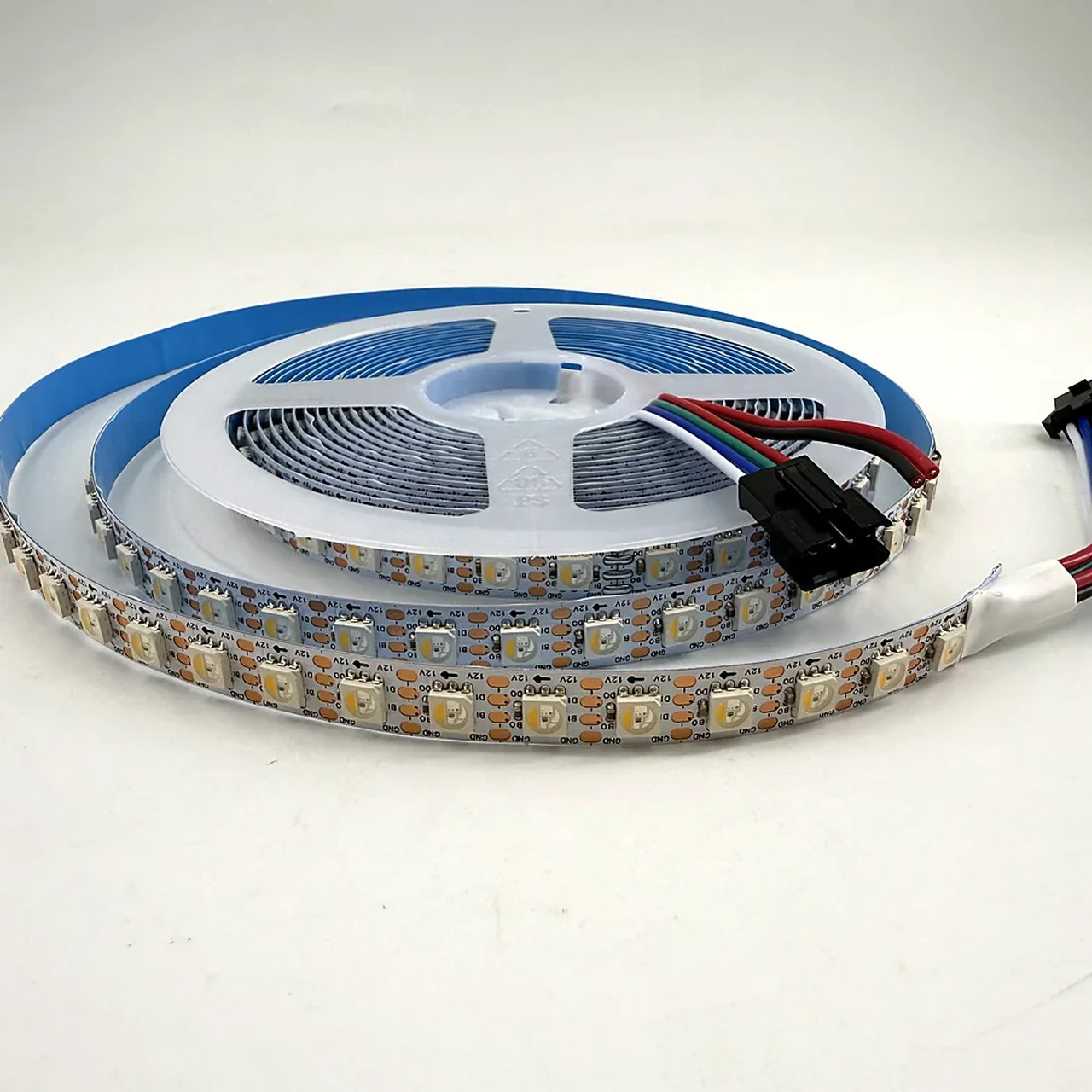
Two details matter on the job sheet. First, WS2811 strips are rated per group of three LEDs — one external IC drives three LEDs, which is why a 60 LED/m 12 V WS2811 strip draws about 14.4 W/m (20 groups × 0.72 W), roughly half the theoretical figure of a 12 V per-pixel chip. Second, an RGBW pixel like the SK6812 adds a white channel: the white diode can draw its own ~20 mA, so full RGBW white costs more than full RGB. If the design calls for white content on a SK6812 RGBW strip, size from the 4-channel figure, not the RGB figure.
An SK6812 RGBW pixel strip: four channels per LED mean the white channel adds its own current at full white.
Per-pixel math scales cleanly to pixel counts: 300 WS2812B pixels at 60 mA each draw 18 A at 5 V. 18 A is a lot of current for a thin PCB trace, which is why the per-pixel figure feeds directly into the next section — and why 5 V runs get power injection long before 24 V runs do. When in doubt, assume full white: effects like chases and gradients average far below it, but the power supply has to survive the static white scene that every client eventually asks for.
Voltage drop and power injection: where the amps actually have to go
Current is what makes power supplies fail on pixel installs, and voltage is what makes current hard to deliver. A strip's copper traces have resistance; the longer the run, the more volts are lost before the far end. When far-end voltage drops below the IC's minimum, pixels shift color, flicker, or stop responding — the classic "bright at the start, dim at the end" symptom. The voltage class of the strip decides how far you can go:
System voltage | Practical run before injection | Why |
|---|---|---|
5 V (WS2812B, SK6812) | ~3–5 m | Every amp loses voltage fast on thin traces |
12 V (WS2811, WS2815) | ~5–10 m | Higher voltage carries more distance per volt drop |
24 V | ~10–20 m | Better still for long architectural runs |
DC48V | Designed for long runs | Current is a quarter of the 12 V equivalent at the same wattage |
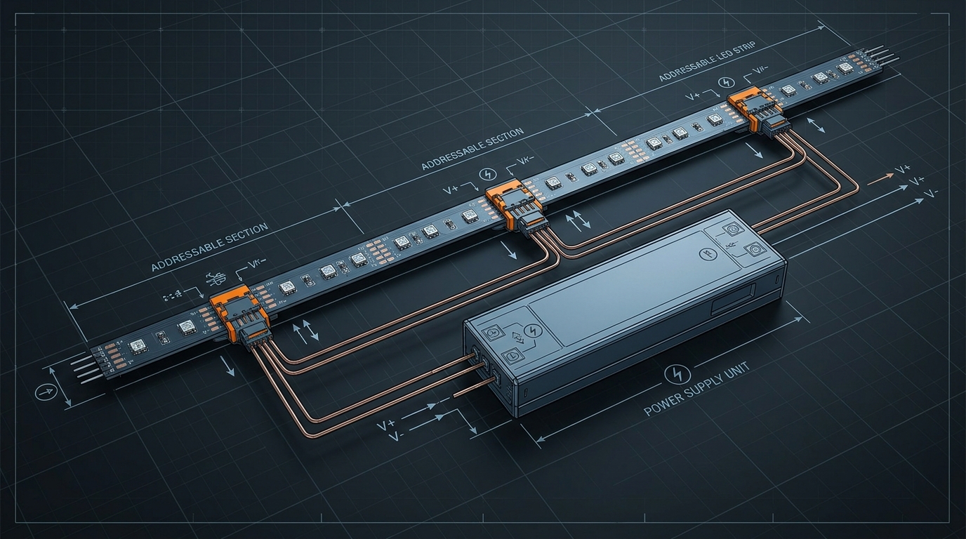
Power injection is the fix: run a second power feed (V+ and GND) from the supply to a point further down the strip, so the far end gets full voltage. Inject every 5 m on 5 V runs, every 10 m on 12 V runs, or whenever the measured far-end voltage sits more than ~10% below the supply voltage. Each injection point needs its own correctly sized wire — the voltage drop across the feed wire itself counts. Use the LED voltage drop calculator on the site to size wire gauge for the run length and current; for injection feeds at 5–10 A, 16 AWG is the usual starting point, and the calculator will confirm it for your distance.
A 12 V pixel run with injection every 10 m: the data signal travels the full length while power is re-fed at intervals.
Every injection branch gets a fuse: a blade or inline fuse rated at ~1.25× the branch's expected current, placed at the supply end of the branch wire. A shorted branch then trips its own fuse instead of taking down the whole install — or worse, melting the wire. If you have ever watched a 5 A short on a 300 W supply smoke a 22 AWG pigtail, you will not skip the fuses on the next one.
For runs longer than a few tens of meters, the cleanest option is often to raise the voltage instead of multiplying injection points. A DC48V pixel strip draws a quarter of the current of a 12 V strip at the same wattage, which is why 48 V systems are built for facade-scale runs — the PILEDS DC48V strip runs 90 LED/m at 21.6 W/m without injection points. The trade-off is that 48 V needs a 48 V supply and — on some projects — a different controller output stage, so it pays to decide the voltage class before quoting, not after the strip arrives. There is a separate family that skips the whole low-voltage problem by running on mains AC; the AC vs DC power design trade-off is covered in a dedicated article.
Controller port budgets and splitting a big run
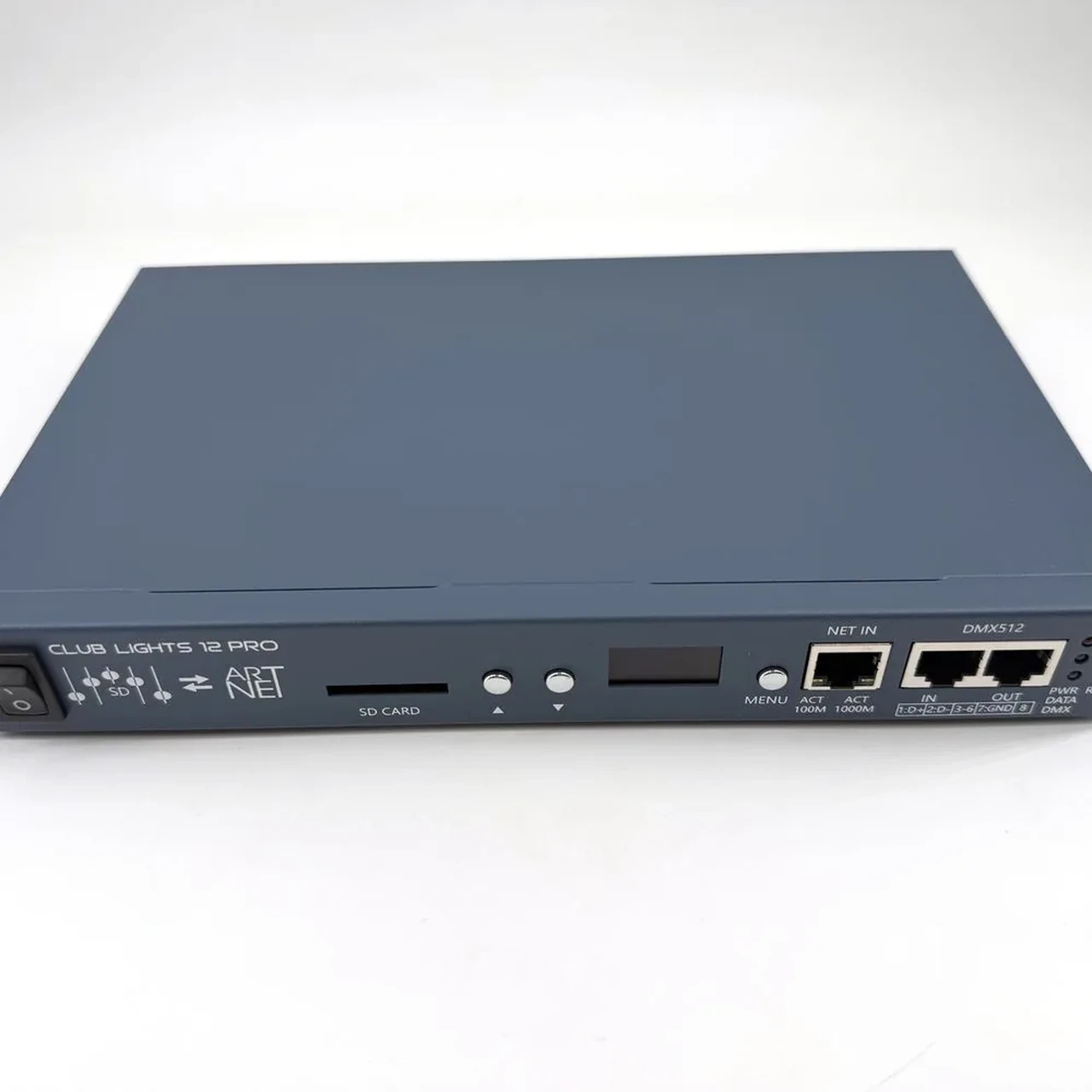
A controller does not power the whole install from one magical output. Art-Net and DMX controllers expose multiple ports, and each port has its own current limit — typically 5 A per port on professional controllers. The port budget is a hard constraint: a 12-port controller with 5 A per port can feed at most 60 A of strip in total, and each port's strip run must stay under 5 A.
That constraint reshapes the sizing. Instead of one big supply, a large install is split into zones — each zone fed by its own supply, each supply wired to a controller port or a set of ports, each port's current summed from the pixels it drives. This is not an inconvenience; it is the correct architecture. Zone-level supplies mean a fault in one zone does not black out the building, supplies can sit closer to their strips (shorter feeds, less voltage drop), and the controller's per-port limit is enforced by construction rather than by hope.
For the budget: add up the per-port currents across all ports (every pixel at full white), confirm the total is under the controller's aggregate rating, then assign power supplies per zone. The Art-Net / DMX controller family lists per-port output specs on each model page — check the port current rating before you divide the run into zones, not after.
A multi-port Art-Net controller: each port carries its own current budget, so the strip is divided into zones to match.
A useful sanity check before you finalize: if the total pixel count of the install demands more amps than the controller can source, the answer is more controller ports or lower-voltage feeds — not a bigger power supply. The supply sizes the zones; the controller sizes the number of zones.
Choosing the power supply: constant voltage, regulated, and certified
The short answer to the most-asked question — can I use a regular power supply for LED strips? — is yes, with three conditions. The supply must be constant voltage (regulated 5 V / 12 V / 24 V / 48 V DC output), matched exactly to the strip voltage, and rated with margin. Pixel strips are constant-voltage loads: they draw whatever current the LEDs demand at the set voltage, so the supply's job is to hold the voltage steady while the current varies. That is what a "regular" LED power supply does, and it is also what rules out two lookalikes:
- Constant-current drivers (the kind that power non-addressable LED strings and modules in series) are wrong for pixel strip. They regulate current, not voltage, and a pixel strip's wildly varying current demand would make the output voltage wander.
- Unregulated transformers / wall adapters (no regulation, output rises when unloaded) are wrong too. Under load the voltage sags; unloaded it overshoots — both bad for ICs that expect a tight voltage band.
So: a regulated constant-voltage switching supply, in the MeanWell-style enclosed metal or DIN-rail form factor, is the working standard for pixel installs. Buy one with the standard protections — overcurrent, short-circuit, and overvoltage — because a pixel strip shorting out is a when, not an if, on a busy install. Add the branch fuses from the previous section and the supply is the last thing that dies.
Two more numbers belong in the quote. Efficiency: quality switching supplies run 85–92%, so a 200 W output supply draws roughly 200 / 0.88 ≈ 227 W from the wall — relevant for the AC breaker and for heat inside the enclosure. On a 120 V circuit that is about 1.9 A of AC input; on 230 V about half that. Certification: for commercial installs, the supply itself should carry the same safety marks the project requires (CE, UL/ETL for US jobs, and so on) — a certified supply is part of the electrical inspection, not an upgrade option.
Bigger is not automatically better. A supply oversized by 3–4× runs less efficiently at light load, costs more, and takes up enclosure space. The 20–30% margin is the sweet spot: enough headroom for heat and transients, not so much that you are paying for capacity the strip will never draw. If the margin calculation lands awkwardly between standard sizes, round up to the next standard rating — 200 W, 300 W, 350 W, 500 W — and move on.
Sizing a power supply for a 30 m pixel LED strip: worked example
A sign shop quotes a 30 m storefront run of 12 V WS2811 pixel neon, 60 LED/m, rated 14.4 W/m, driven by an 8-port controller with 5 A per port. End to end:
- Total wattage: 30 m × 14.4 W/m = 432 W at full white.
- Margin: 432 × 1.2 = 518 W → round up to two 300 W supplies (600 W total), not one 600 W unit — see step 4.
- Current per supply: each 300 W supply at 12 V can deliver 300 / 12 = 25 A continuous; at 80% load, ~20 A of strip per supply.
- Zones: 30 m / 2 supplies = 15 m per supply. At 14.4 W/m, 15 m draws 216 W ≈ 18 A — inside the 20 A derated supply budget. But 18 A cannot ride on two 5 A controller ports, so each zone splits into four sub-runs of ~3.75 m (≈ 4.5 A each) → eight ports total on the 8-port controller: 8 × 5 A = 40 A of port capacity versus 36 A of total draw. Each sub-run is short enough to need no mid-run injection; it gets its own 16 AWG feed from its port, fused at 6 A (4.5 A × 1.25 ≈ 5.6 A, rounded up to the next fuse size).
- Verify on site: after wiring, measure the far-end voltage of each sub-run at full white. Within 10% of 12 V — done. Below that, move the injection point closer or step the feed wire up a gauge.
The same five steps scale to any install: size the total with margin, split by controller port budget, feed each zone from its own supply, inject and fuse by run length, and verify with a multimeter at full white. The power supply is the one component you can afford to over-spec by exactly one standard size and no more — and the one component you cannot afford to get wrong, because it is the only part of a pixel install that carries the full load of every LED on the run.
When the spec sheet gives you a W/m figure and you want to double-check the math against your own pixel count — or you need a quote that matches the strip, controller, and supply into one BOM — send the project details over and the PILEDS engineering team will size the power package with you, free samples for qualified projects included.
Specifying pixel LED for a real project?
Send the spec — pitch, IC, IP class, run length, voltage — and you get an engineer's answer, not a catalogue. Samples and OEM/ODM quotes from the Shenzhen factory floor.