
Choosing an LED Aluminum Profile That Won't Block Light
Most LED aluminum profiles do not fail on looks; they block light. Here is how cover, depth and strip fit decide how much of your strip's output you keep.
The profile is usually the last line added to a lighting material list, and the first thing that turns a bright strip into a disappointing line. Nobody orders a dimmer strip on purpose. They order a profile, and it quietly takes a share of the output. An LED aluminum profile is an extruded aluminum channel that holds a length of LED strip behind a diffuser cover and closes the ends with end caps; the extrusion gives the strip a straight, protected housing and a heat path, and by its geometry it also decides how much of the strip's light reaches the room. Choosing one is a light-budget decision before it is an aesthetic one — and the numbers behind it are yours to check before you order.
Why an LED aluminum profile is a light-loss decision, not a housing choice
A profile sits between the LED and the viewer. Light leaves the strip, meets the cover, meets the channel walls, and only then arrives at the surface being lit. Each of those interactions can spend output. A profile never adds light; it trades light for a straight line, protection, an even face and a thermal path. Four trades are worth naming before you open a catalogue, and each has a question attached that a supplier can answer with a value rather than an adjective.
Mounting style and finish are what a catalogue leads with, and they are real selection filters — but neither changes the light budget, so settle them after the four trades rather than before. The mounting decides how much lip stands above the strip. A surface-mounted section is the simplest case; a recessed or flanged one hides the edge of a ceiling or a milled groove, and its flange shades the outer field unless the strip is set back, while a corner section aims the output along a 45° face instead of straight out. The finish is an optical choice too: black absorbs stray light the way dark surfaces do, while white sends more of it back through the cover.
The loss point | What it costs you | Where it hurts most | The question that settles it |
|---|---|---|---|
The diffuser cover | Scattering inside the cover, so the light leaving the face is well below the bare strip's output | Long runs where every lumen was budgeted | What is the cover made of, and what light transmission does the maker publish? |
Emission direction and width | A strip that fires sideways under a top-view lid, or a PCB plus coating that is too wide or too thick to seat properly | Side-mounted runs, signage, sealed IP tape | Which way does my strip emit, and how wide is it with its coating on? |
Depth, standoff and the lip | Even light is bought with light: a deeper seat means more scattering and more rays cut off by the channel walls | Cove and wall-wash lines seen from close range | How deep is the channel, what is the LED pitch, and how high is the lip above the seated strip? |
Heat and sealing | Heat that cannot leave through the mounting tape, and a water rating that belongs to the assembly rather than to the channel | Higher-output strip, outdoor and wet locations | What does the strip sit on thermally, and who owns the IP rating once the ends are gasketed? |
The table is the article in miniature; what follows is how each row behaves.
A profile never adds light. The only honest question is how much it takes, and whether the line, the protection and the heat path it gives back are worth that price.
The diffuser cover is where most of the light goes
A profile cover is an optical diffuser doing two jobs at once. The scattering is what removes the dots and softens the glare of forty small emitters in a row; the scattering is also what removes light. No cover hides the LEDs completely and passes all the output, because hiding them and losing output are the same physical act seen from two sides.
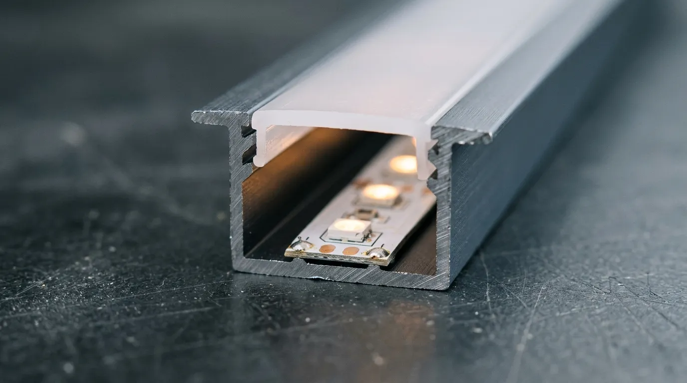
Above: the strip sits below the cover, not against it — the gap is the standoff that buys an even line, and also the depth the walls can shade. Illustrative render, not a photograph of a specific product.
What changes between covers is how much survives, and the published numbers differ by supplier — so take any single ladder as that maker's own figure, not an industry constant. One profile supplier's guide gives clear covers 85–95%, semi-clear 70–80%, opal or milky 30–40%. A second supplier's buying guide gives clear 90–98%, frosted 80–90%, opal 60–70% and milky 50–60%. A third supplier's cover comparison gives clear 90–95% and diffused covers 60–70%. The opal row alone therefore spans 30–70% across three published catalogs — a two-to-one spread on the one choice that decides most of the budget. The material sets the order of magnitude; the part sets the number. PMMA (acrylic) transmits up to 92% of visible light at 3 mm thickness and filters ultraviolet below roughly 300 nm, but it is brittle and scratches easily; polycarbonate is the impact-tough option, at the cost of a softer surface that needs a hard coating. A clear cover can come close to what PMMA passes on its own; an opal cover has deliberately given a large share of that away, and the only figure worth buying against is the one your supplier publishes for the exact cover you order.
Cover | Published transmission (makers differ) | What the line looks like | Where it belongs |
|---|---|---|---|
Clear / transparent | ~85–98% | Maximum output, individual LEDs and hot spots visible | Long throws, wall-wash and grazing runs where the strip leaves the sight line |
Frosted / semi-clear | ~70–90% | Soft line, faint dots still readable at close range | General accent and cove runs, retail and cabinet work |
Opal / milky | ~30–70% | Dot-free line even at arm's length | Close-viewed faces, display and reception work, anywhere the eye lands on the fixture |
Bands are the union of the three published ladders above; a single maker quotes a narrower one, so the number to buy against is that maker's figure for the cover in front of you.
So it is a decision, not a compromise: when a run needs a clear cover's output and an opal cover's smoothness, the lever is the strip. Denser strip, a COB strip whose light is continuous to begin with, or a strip built with its own diffusing lens can buy evenness without asking the cover to do it alone. The cover also faces sunlight: on exterior runs, check UV stabilization before you order.
Match the aluminum profile for LED strip to the strip itself
The second loss point is geometric, and it gets missed because profile and strip are usually bought from two different pages. Start with direction. A plain strip LED is typically rated around a 120° beam angle, directed perpendicular to the mounting surface. Lensed and wide-angle strip products are published wider — the two strips linked in this article both carry a 180° beam angle — and a wider cone is not automatically friendlier here: fired into a narrow channel it puts more of its output on the walls. By contrast, 'side view' or 'edge emitter' SMDs are built so light leaves parallel to the tape's adhesive face — the property that makes side-mounted and edge-lit work possible. Put a side-emitting strip under a top-view U channel and the lid sits between the emitters and the room: the profile blocks the light it was bought to deliver, and extra strip power does not fix geometry. The fix is the right section — a profile that carries the strip on its edge, or a side-view strip with an integral lens that does the same job in less space.
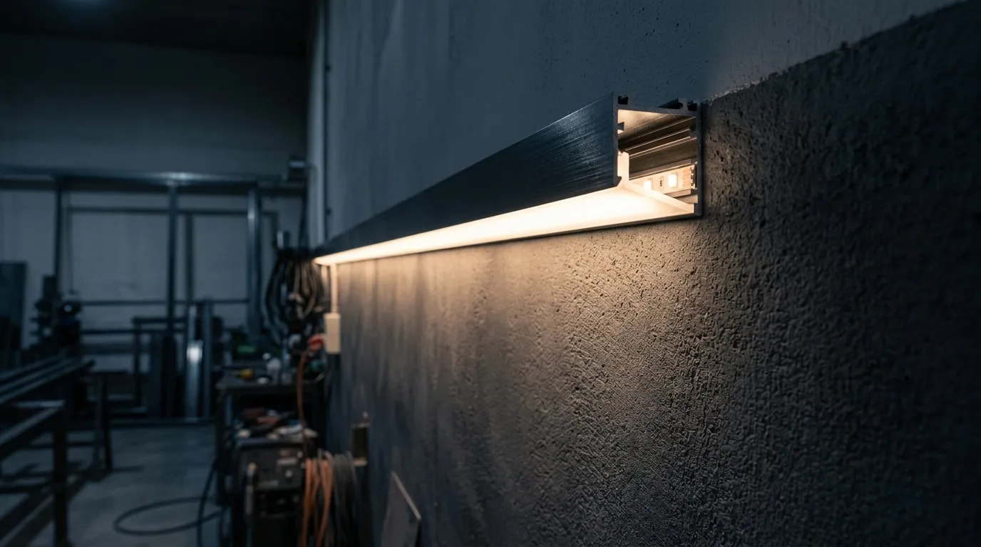
Above: a side-emitting strip in a corner profile — the light leaves parallel to the mounting surface, so the section has to be built for it. Illustrative render.
Then check width and thickness, which are never just the PCB figure. Water-resistant tape is encapsulated in silicone or epoxy, and encapsulation adds millimeters in both directions. The same product in its bare form and its IP65-coated form (IP30 vs IP65 vs IP68) are not interchangeable in a shallow channel: the coated version can sit proud of the internal shoulder so the cover presses onto it, or ride high enough that the lip shades the outermost emitters. Measure the strip you are actually buying, coating included, and leave a millimeter or two of clearance.
Two more mismatches are worth a check. Wide and multi-row strips need a wider channel, because the lip's shadow falls hardest on the outer rows. And a bendable or S-shaped strip folds sideways where a rigid channel cannot follow, so a curved run gets a bendable channel or gets segmented corners with visible joins. If the strip is addressable there is one more constraint: a diffuser turns a small source into a large one, which is the opposite of what a pixel needs. Behind an opal cover, adjacent pixels overlap, the contrast between lit and unlit falls, and the display reads flatter than the same strip on an open mounting. Where the strip exists to be read as pixels, the cover is a decision taken at the start, not an accessory added at the end.
Depth buys uniformity with light — and the lip takes its cut
A diffuser can only smooth what reaches it. Each LED is a small source, and illuminance falls with the square of distance from it, so the ratio between "directly under an emitter" and "between two emitters" flattens as the cover moves away (inverse-square law). That is the whole reason a deeper channel looks more even: not the aluminum, the standoff. The ratio that matters is standoff divided by LED pitch, so the same depth is smoother on a dense strip, and the same strip is smoother in a deeper channel.
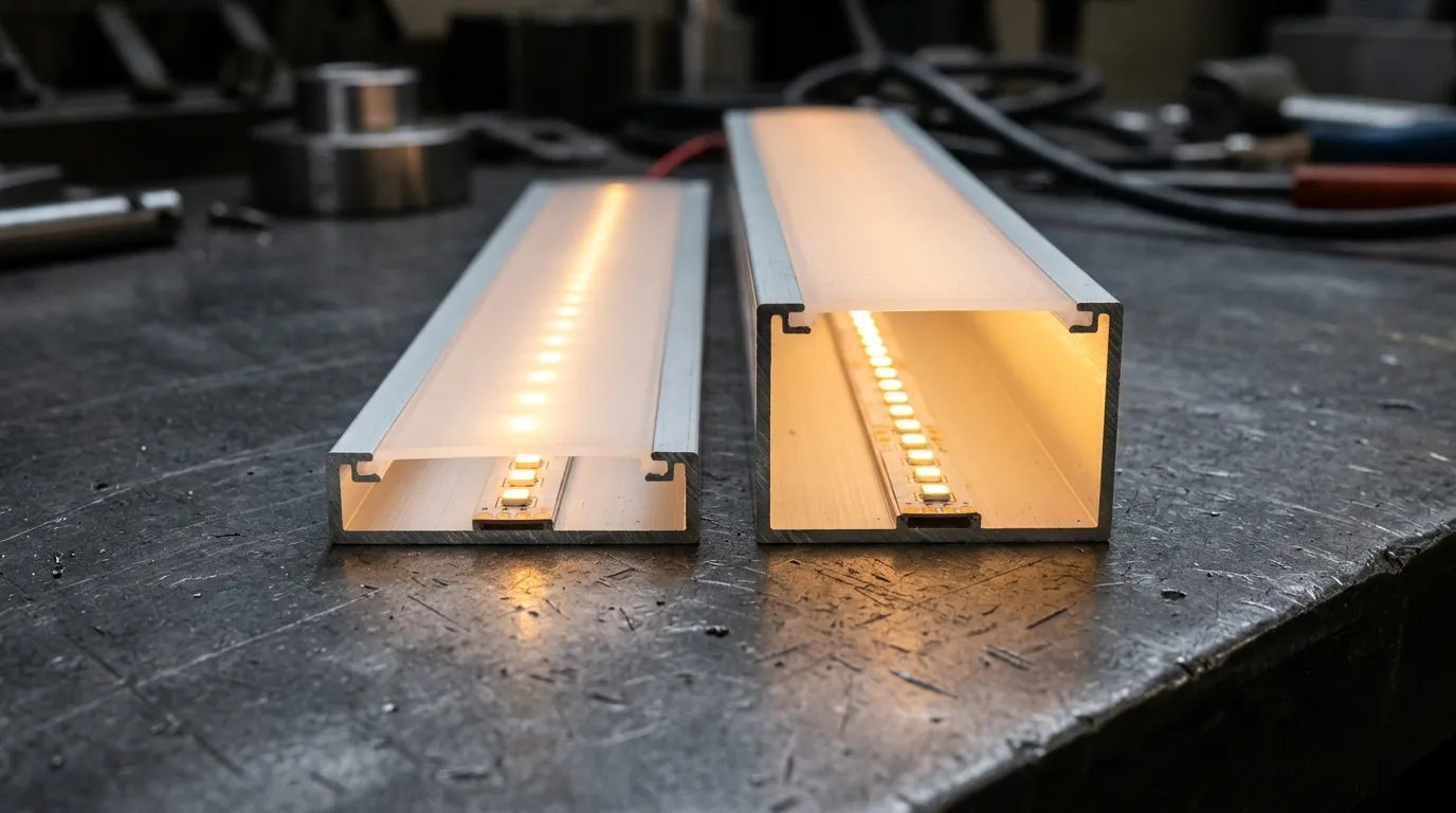
Above: same strip, two depths — the deeper seat evens the line out, and takes more of the output doing it. Illustrative render.
The bill arrives as the third loss point. A deeper seat means more emitted light strikes the walls before it leaves, where it is scattered again rather than delivered. It also means more of the beam is cut off: a 120° cone fired from inside a narrow slot has rays that never clear the aperture, and that share grows with depth and with any lip or flange standing above the seated strip.
You want | The cheap move that costs light | The move that keeps light |
|---|---|---|
A dot-free line in a shallow channel | Swap in an opal cover and lose 30–70% of the output, depending on the cover quoted | Raise the strip density or use a COB strip so there is less to hide |
A bright line with a visible dot pattern | Deepen the channel to spread the dots | Keep the depth and accept the dots, or move the fixture further from the viewer |
Maximum output on a wall-wash run | Remove the cover entirely and expose the emitters | Keep a clear cover, aim the strip away from the sight line, and control the viewing angle |
Two rules survive every project. Set the strip below the internal shoulder so the lip cannot cut the beam, and choose uniformity by strip density before you choose it by channel depth. The strip side of that trade — what pitch and density do to appearance, and how they interact with power — is covered in our pixel LED strip buyer's guide; the profile side is the arithmetic above.
Heat, sealing and the numbers to demand before you order
The fourth loss is not optical, and it decides whether year three still looks like month one. An aluminum channel is a heat spreader, which is why a high-output strip belongs in one: most of the electrical power going into an LED becomes heat rather than light, and junction temperature sets both output and life (thermal management of high-power LEDs). The heat leaves along one path — die, solder, board, interface, aluminum, air — and the weakest link is usually the interface, because the same double-sided tape that holds the strip is the layer the heat has to cross. On a heavily loaded run, that is the part to upgrade, not the wall thickness of the extrusion.
The aluminum surface deserves one correction too, because "anodized" is often offered as a thermal argument. Anodizing is a corrosion and appearance finish: the anodic layer is electrically insulating and has a much lower thermal conductivity than the aluminum beneath it, and it cracks under thermal stress above roughly 80 °C (anodizing). It is thin, so it is no deal-breaker on a normal run, but the decorative finish is not where the thermal advantage lives.
Sealing is the other half, and where specs most often drift. A standard channel is not an enclosure, and IP numbers are test definitions rather than marketing words: the first digit covers solids, where 6 means dust-tight under a vacuum test; the second covers water, where 7 means immersion up to one meter for 30 minutes and 8 means continuous immersion at a depth the manufacturer specifies; ratings above IPX6 are not cumulative, and the standard test uses fresh water (IP code). Read that against the common claim that a channel with a silicone plug and glued end caps is "IP65": the rating belongs to the assembled fixture, not to the loose channel and not automatically to the strip. If the project needs a rated fixture, buy the rated strip and get the assembled rating in writing. If the run is sheltered, say so — a bare strip in a gasketed channel can be the right answer.
None of this needs a laboratory. It needs six answers in the quotation, and any supplier who builds profiles and strip should have them:
- Cover: the material (PMMA or polycarbonate) and a published light transmission value, not just "frosted".
- Geometry: internal width, internal depth, and the height of the lip above the seated strip.
- Fit: the strip's real width and thickness including its coating, against that internal width.
- Thermal: what the strip sits on, and whether the maker rates the assembly for your output.
- Sealing: whether the quoted IP applies to the strip, the channel, or the assembled fixture — and where the ends are closed.
- Mechanics: mounting clips or brackets, end caps, joiners, the maximum length supplied in one piece, and how cut lengths are joined so the joints do not read as dark gaps.
If you are sourcing the strip and the accessories together, tell us the layout, the viewing distance, the environment and the control protocol, and we will come back with the running package to match. The full pixel LED accessories guide collects the rest of the cluster, including power and connectors; if the electrical side is still open, sizing a power supply for pixel LED strip is the place to start.
Choose the cover by viewing distance, not by the trend in the catalogue. Match the channel to the direction your strip emits and the width it actually is. Then set the depth by how even the line has to be, and accept the output that costs. A profile that blocks light is rarely a bad extrusion; it is a good extrusion chosen without the light budget in mind.
Specifying pixel LED for a real project?
Send the spec — pitch, IC, IP class, run length, voltage — and you get an engineer's answer, not a catalogue. Samples and OEM/ODM quotes from the Shenzhen factory floor.