
LED Neon Flex Bending Radius: Top, Side & 3D
The bending radius of LED neon flex is a pair, not a number: the plane it is built to bend in and the cross-section doing the bending. How to check both.
A flexible neon profile does not have a single bending radius. Ask for "the" number and you will very often be handed one that belongs to a different cross-section, a different bend plane, or a different unit entirely — and the sources ranking for this question today do not agree with each other on what the number even is. What a neon flex will take is a pair: the plane it was built to bend in, and the cross-section doing the bending. Get the pair right and a tight curve is a forming job. Get it wrong and the failure shows up weeks later inside the profile, where nobody can see it.
That is what this page answers, in the order the question comes up on a real job: what the number actually limits, why the published figures disagree, which plane a profile is built for, how to establish a radius you can defend, and what happens when you go past it. If you are still choosing between flex and pixel strip for the sign itself, that decision lives in the signage and channel letter selection guide.
What the bending radius actually limits
A bend radius is the radius of the arc a part is formed to, measured to the inside of the curve. Around any bend, the material on the inside is compressed and the material on the outside is stretched, with a neutral axis in between that does neither. Radius and diameter get used interchangeably in this trade and they are not the same figure: a stated diameter is twice the radius, so a supplier quoting Ø60 mm and a supplier quoting R60 mm are describing arcs that differ by a factor of two. Whichever number you are given, find out which one it is. Half the confusion in this topic starts there.
The material being bent inside a neon flex is not one thing. Three layers set the limit, and only the first is visible from the outside:
- The jacket — the extruded silicone or PVC body that carries the light. It has to flex without whitening, cracking, or separating from the flat backing strip it is bonded to.
- The internal board — a slender flexible circuit carries the LEDs and their solder joints down the length of the profile. Copper tracks and solder are the least forgiving materials in the assembly, and the board is not centered: it sits along one wall of the extrusion. That off-center seating is the whole reason bend direction exists as a specification.
- The LEDs and the diffuser wall in front of them — the standoff between the light sources and the glowing face is what makes a neon flex read as one continuous line rather than a row of dots.
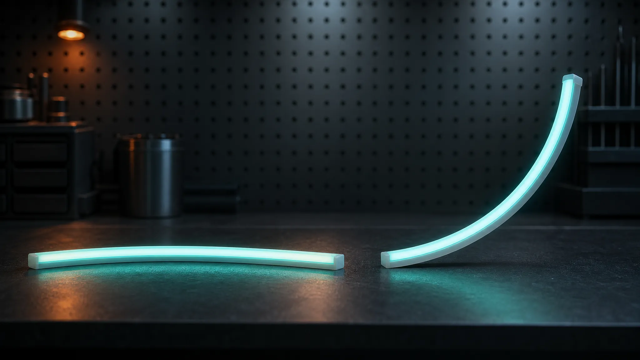
The same profile, formed in two planes. The flat bend follows the mounting surface; the rising bend leaves it — and only one of the two matches how the board is seated inside the extrusion. (Illustrative rendering.)
Mechanically, the inside of the arc is where the trouble starts: the board's tracks sit on the compressed side, and the diffuser wall between the LEDs and the face thins. None of that is visible on a finished sign, which is why a bend that was too tight on the bench often survives the install and fails later — light works on day one, dead section after a few months of thermal cycling.
Neon flex bending radius: the number is a pair, not a value
Search for a neon flex bending radius and you will find published figures that do not agree with each other. They are worth reading, because the way they disagree tells you what the number actually depends on. Every figure below is a vendor claim published on the page named; none of them is traceable to a test report, and the sources were live when this article was written:
Published claim | Figure as stated | What it is attached to |
|---|---|---|
Neon flex radius guide (Mihoray) | 50 mm top-bend · 80 mm side-bend | "standard silicone neon flex" |
Top/side/3D bend FAQ (AIDIWATT) | top bend "usually ≥ 60 mm" · side bend "usually ≥ 80 mm" | silicone neon flex, by bend direction |
Datasheet, ICL Halo Mini (IC Lighting) | "Bending Radius: 60mm" in the spec block — then "minimum bending diameter of 60mm" further down the same document | one product, one document |
Per-model engineering table (SuntechLite) | 360° Ø18/23 mm → R>60 mm · 360° Ø40 mm → R>100 mm · 10×10 top-bend → R>60 mm · 4×10 and 6×12 side-bend → R>30 mm · 10×20 side-bend → R>60 mm | twelve named profiles, by axis and size |
Bend notes by bend type (Arraystar LED) | inside bend 25 mm · outside bend 50 mm · 90-degree corner 50 mm radius | neon flex, tabulated by bend type |
Two things fall out of that table.
First, the unit problem is real, not pedantic. The IC Lighting datasheet calls one figure a radius and a diameter on the same page. That is the document, not a careless reader. Any figure you are given for a neon flex should arrive labeled R or Ø, and if it does not, the honest reading is that you do not have a number yet.
Second, and more useful: the axis alone does not decide the figure. The two most quotable guides say side-bend is the looser one — 80 mm for side-bend against 50–60 mm for top-bend. The only per-model table in that set says the opposite for slim profiles: a 4×10 mm or 6×12 mm side-bend profile bends to R>30 mm, tighter than any top-bend profile the same table lists. Both statements can be true at once. What is changing is the cross-section, and it is the bigger lever of the two:
- Bend the same profile family and the required radius tracks its largest cross-section dimension in the plane of the bend. Slim profiles bend tight; deep ones do not.
- Within one cross-section, the plane that the board was seated for can be formed tighter than the plane it was not — because in the wrong plane you are loading the tracks in their stiff direction.
- Jacket material moves the figure at the margin. A silicone profile tolerates a tighter form than a stiff PVC one, and PVC stiffens further as it gets cold — a real effect in an unheated workshop in winter, and one that no catalog figure accounts for.
So when a supplier says "it bends fine", the useful reply is not "how far?" but "which profile, which plane, and is that radius or diameter?" Those three answers turn a claim into something you can put on a drawing.
Rule of thumb: a radius figure without a plane and a unit is not a specification. Get both in writing before anything is formed.
Top bend, side bend and 3D bend: read the plane off the profile
The bend plane is not something you choose at the bench. It is set at the factory by where the internal board sits inside the extrusion, and it is usually visible in the profile's own name. Forcing a profile into its wrong plane is the one mistake that damages a run immediately rather than eventually.
Top bend (vertical bend)
A top-bend profile carries its board along the flat back of the extrusion. The run curves up and down in the vertical plane — over a cornice, along the underside of a canopy, around the top of a letter. The flat back is part of the design: it sits into a routed groove or against a backing and locates the run. Twist a top-bend profile and you are loading the board across its narrow axis, which is where a run goes dark in one spot rather than dying cleanly.
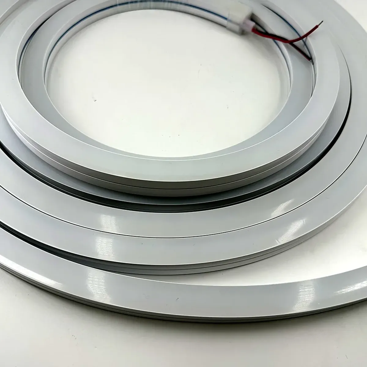
The flat back of the extrusion is what locates a top-bend run in its groove — and what has to stay flat while the profile curves.
Side bend (horizontal bend)
A side-bend profile has its board sitting against one vertical wall, so the extrusion turns left and right within the plane it is mounted on. This is the plane that letters, logos and storefront outlines generally need, because the run has to follow a shape painted on a flat surface without climbing off it. It is also the profile to reach for when the customer's drawing has a curved return or an arc that a top-bend run would have to fight.
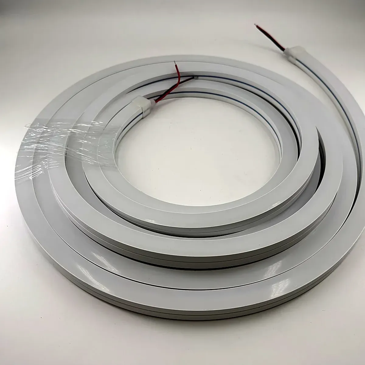
Flat concentric loops on a tabletop: the side-bend plane, where the whole run stays in the plane of the mounting surface.
One naming trap worth flagging: "side bend" is used both for a neon flex profile and for flat LED tape with a side-emitting lens. The tape version is a different product with a different limit, and its visible-light question belongs with the aluminum profile guide rather than here. Throughout this article, profile means the neon flex extrusion cross-section — not an aluminum channel.
3D bends and 360° profiles
A genuinely three-dimensional bend turns in more than one plane over the same run — the classic S in a script letter, a spiral, a helix around a column, a logo whose tail sweeps out of the mounting surface. A single top-bend or side-bend profile can be persuaded part of the way, and the persuasion is exactly where the damage happens. The clean answer is a different profile: a 360° extrusion, where the light path is built symmetrically so the run can follow a curve in any plane, or a shorter-radius slim profile where the arc is tight but still flat.
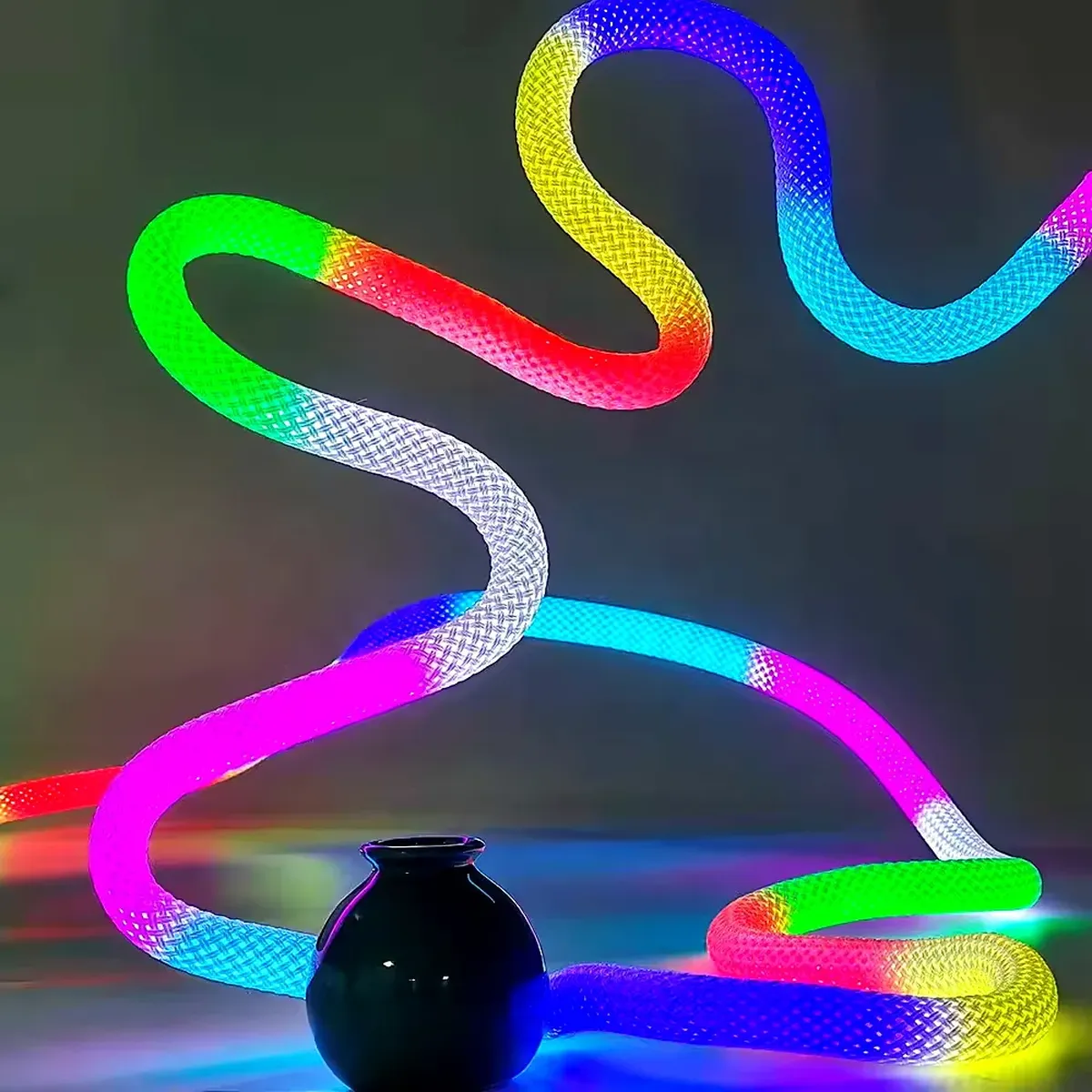
One run, two planes. This is what a 360° profile buys you, and why a mixed-axis curve should change the profile rather than the technique.
Practically, the range spans slim 12 × 06 mm profiles at the tight end, 16–20 mm profiles in the middle — the site's named side-bend model sits here — and round 360° extrusions at 30 mm and 40 mm for the bends that turn in both planes. Which is why the axis is the first thing to pick and the radius the second.
Minimum bend radius by profile size: how to establish the number you can defend
The reason a chart of radius by profile size is hard to trust is that four variables move at once. A figure published for "silicone neon flex" is a figure for one cross-section, one board seating and one temperature. Change any of them and the number moves.
Here is what actually drives it, in the order of influence:
- Cross-section in the bend plane. The deepest dimension the profile has to wrap around is the dominant term. This is why a slim 6 mm profile and a 40 mm round extrusion cannot share a number.
- Board seating. Whether the tracks sit on the compressed or the stretched side of the arc for the bend you are making. Same profile, different plane, different limit.
- Jacket and its temperature. Flexible silicone takes a tighter cold form than PVC; PVC also stiffens as the workshop gets cold, so the same bend can pass in summer and crack in February.
- LED pitch and the diffuser standoff. Not a hard mechanical limit, but it decides how tight a bend still looks right, which for a sign is the point.
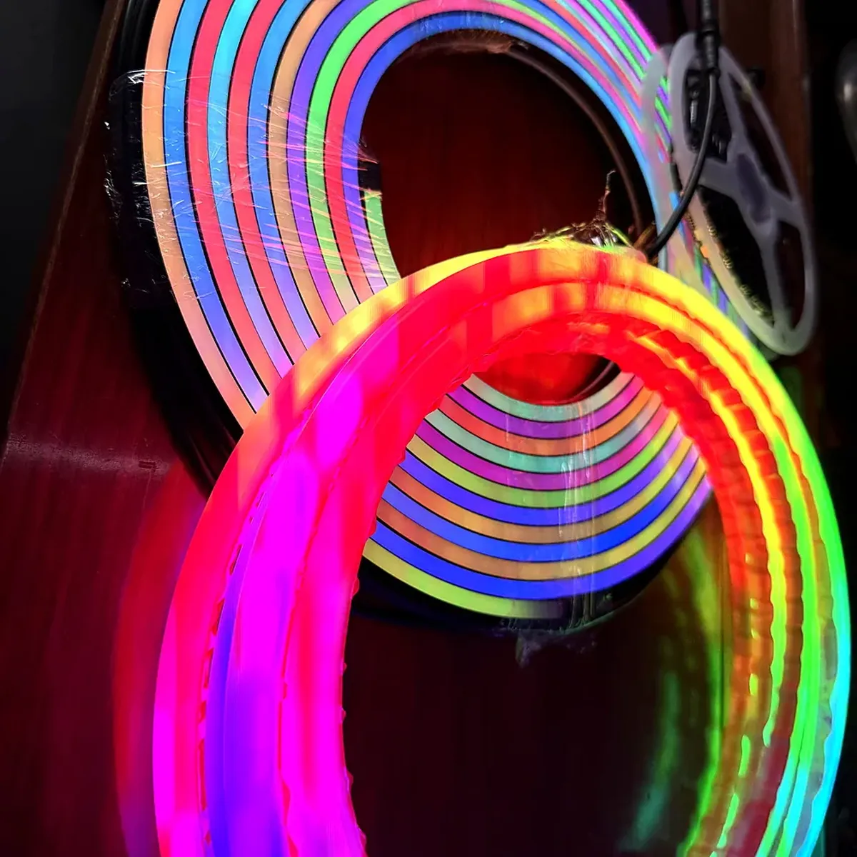
The variables in that list, side by side: profiles differ in cross-section and in jacket.
Because none of that is captured by a single catalog figure, the number worth having is the one your supplier will put in writing for the exact profile and plane you are ordering. Five questions get you there, and every one of them is answerable in a single email:
- For this profile, what is the minimum bend radius in millimeters, and is it R or Ø?
- Which plane is the profile built to bend in — top, side, or 360°?
- What is the cross-section in millimeters, in the plane of the bend?
- Is that figure measured on a test length, or a catalog figure for the family?
- If the finished bend is tighter than the figure, what happens to the warranty?
Question four is the one that separates the answers. A measured figure comes with a test length and a plane; a catalog figure tends to arrive as "typical industry standards", which is a fair description of a family and not a specification for your run. If the reply is vague, establish it yourself: form a short offcut of the actual profile around progressively smaller templates, hold each form for a few minutes, and inspect the arc after each step for the first hint of whitening on the outside face or a lifting backing. The radius at which that appears, with a margin, is the number to write on the drawing.
What over-bending does: from a cracked trace to a wet sign
Past the limit, the failure is not one event. It is a chain, and each link is quieter than the last.
The tracks and joints go first. Bend beyond the profile's limit and the copper tracks and solder joints on the compressed side of the board are the components that cannot follow. That is the mechanism behind the cracked pads and dead LEDs that strip suppliers describe from their own benches — the same note that publishes the 25 mm inside-bend figure states the mechanism plainly: inside bends compress, outside bends stretch. A bend that looked fine at install dies weeks later. The jacket, which is the part everyone watches, is more forgiving than the board inside it.
Then a segment drops. One addressable group or one series group stops working, and it reads as a dark spot, a flicker, or a dead stretch at the tightest point of the curve. At this stage the sign still looks broadly right from ten meters away, which is why the problem usually gets reported later rather than immediately.
Then the jacket separates at the outside of the arc. Sustained tension on the outer face works against the bond between the extrusion and its backing, and once that bond lifts you have a gap running along the profile.
Then the seal fails, and the rating goes with it. This is the part with commercial consequences, because IP ratings are certified on the profile as supplied, not on the profile as you formed it. A bend that breaches the jacket takes the assembly back below its tested class, and water that gets in at the outside of the arc reaches the board from the direction nobody insulated. The rating scales themselves belong to a separate discussion — the IP rating guide covers what each class survives; the point here is narrower: a bend can cost you a rating the factory paid to test.
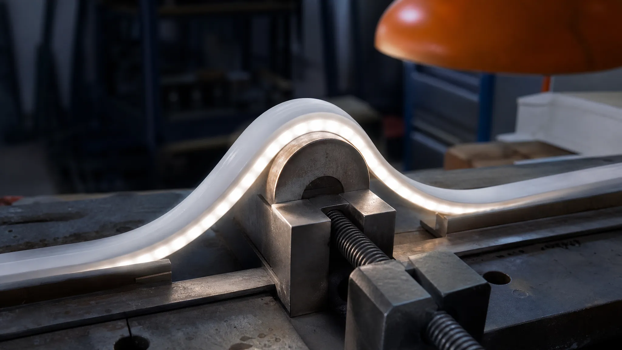
Where to look first. The inside face at the apex takes the compression; the outside face takes the stretch. Check both before the run goes into the letter. (Illustrative rendering.)
Warranty sits at the end of the chain: over-bending is treated as installation damage rather than a product fault, which is why the written radius figure matters more than the price of one extra meter of profile.
The inspection point: after forming, look at the inside face at the apex for a spot that reads dimmer or uneven, and at the outside face for a stretched or whitened jacket. Either one is the first link of the chain above.
Why a tight bend dots on the inside
Even when the mechanics survive, a tight bend can still look wrong. The even glow of a neon flex comes from the standoff between the LEDs and the light face. Bend the profile and that geometry stops being uniform: the diffuser wall thins on the inside of the arc and thickens on the outside, so the same LED pitch no longer produces the same evenness across the curve. In practice the dots start to read at the tightest part of the run first, on the side facing the inside of the bend.
Two fixes, and both are profile decisions rather than forming decisions. Go to a denser profile — more LEDs per meter, so each one has less arc to cover — or open the radius and take the curve with a joint instead. If the design cannot give either, a 360° or slim profile will often look better at the same radius, because the light path is symmetric inside it and the standoff does not change through the arc.
Tight corners and 90° returns: four ways past the radius limit
The 90° corner is where this article earns its keep, because it is the shape where the honest answer is almost never "bend it". Four routes, roughly in order of how much they cost:
- Change the plane. If the corner turns left or right across a flat surface, a side-bend profile makes it in one piece where a top-bend profile would have to be forced. This is the cheapest fix and it is a specification change, not an installation technique.
- miter the run at a joint on a straight. Two sections meeting at an angle, with the joint placed where the profile is straight and the seam can be hidden by the letter's return or a service loop. The on-site cutting and sealing procedure covers making that joint properly; bending is not a substitute for it.
- Use a factory pre-formed corner or a corner module. The bend is made at the factory with the tooling and the inspection that a bench cannot reproduce, and the joint lands on straight sections where it is easy to keep sealed.
- Move to a smaller-radius profile. A slimmer cross-section takes a tighter arc for the same technique, at the cost of output per meter and a slightly different look. On a deep 40 mm profile this is often the only route that keeps a single run.
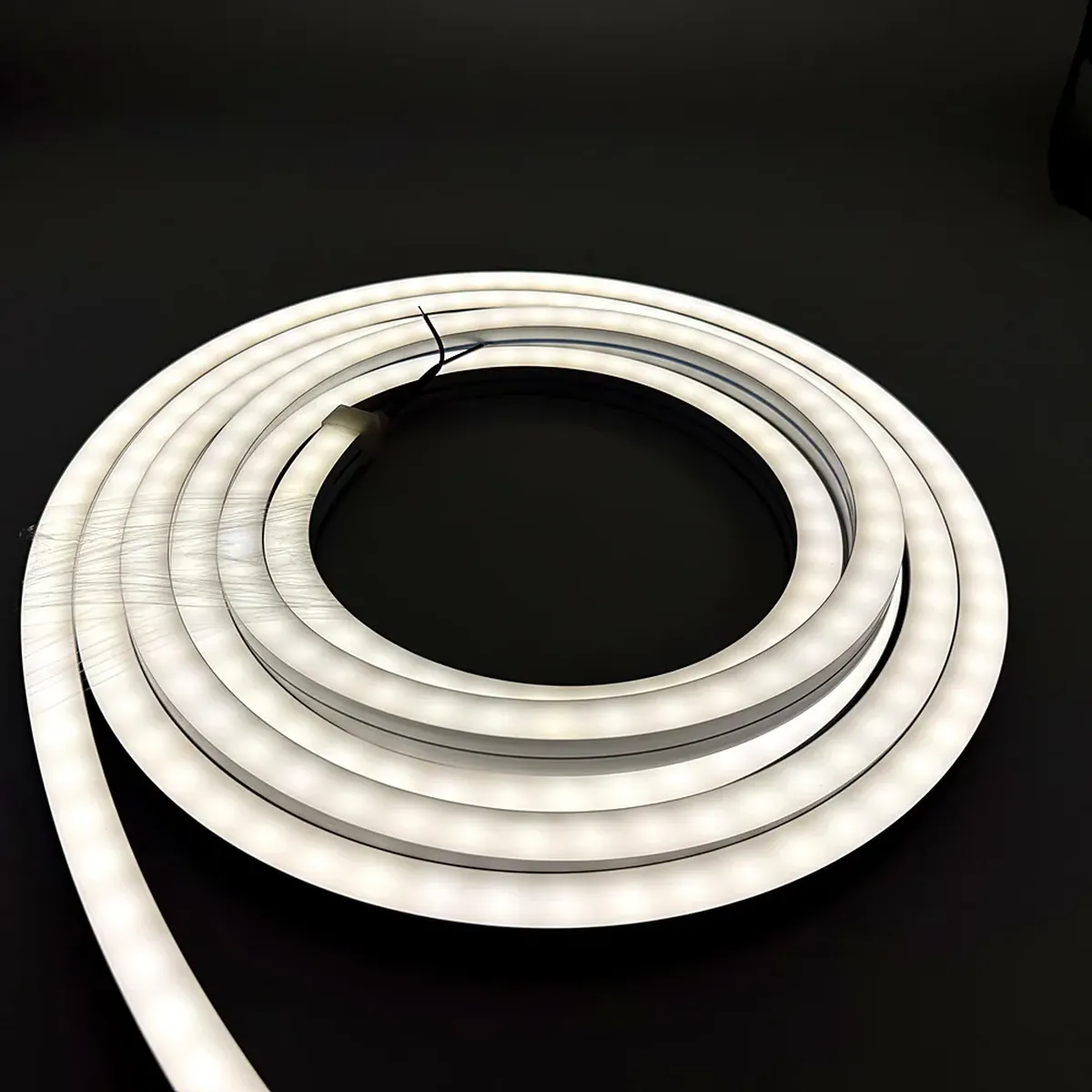
Continuous arcs, taken one at a time. A tight run is formed like this — the curve is walked round, never creased into place.
What none of the four involves is folding. A fold concentrates the entire deformation into a few millimeters of jacket and board at one point, which is the fastest way to break a track — and the guides that discuss folding all say the same thing, for the same reason.
At the bench: cold forming, a jig and when heat helps
Forming practice is the least documented part of this job and the part most shops learn by ruining a length. Three habits carry most of it.
Form to the arc, not to the point. Draw the profile progressively around a template or jig rather than pushing the apex into shape. The bend you are making is a curve, and the profile prefers to be walked into it. A simple mandrel or a plywood template cut to the inside radius does the job — the tooling matters far less than doing it gradually.
Hold the form while it settles, then release and check. Silicone returns a little when you let go; PVC creeps more and takes longer to settle. Clamping a formed bend against its template for a few minutes stops the run springing out of the letter groove on the second day.
Treat heat as the last resort, and ask first. Warming the jacket lets a stiff profile take a rounder form, which is useful on a cold workshop floor. But heat softens the jacket; it does not make the board inside more flexible. Overheat it and you can dull or mark a silicone surface, and heat forming is the classic argument in a warranty conversation. If you want that option on a job, get the factory's position on it before you buy, in writing.
Two things not to do. Do not twist a profile to make a curve work — a twist loads the board across the direction it was seated for, and the result is a dark spot rather than a graceful failure. And do not form a cold PVC profile in an unheated workshop: the same bend that behaves in a warm shop can crack in a cold one, and that difference is on no spec sheet.
What to write on the order and the shop drawing
Most of this article collapses into one line on a purchase order. The shops that never argue about a return radius are the ones that put five items on it:
- the profile, named precisely enough to fix the cross-section;
- the plane per run — top, side, or 360°;
- the inside radius (R, in mm), as the number the supplier confirmed in writing;
- the corner treatment at each turn — formed to the radius, mitered at a joint on a straight, or a factory pre-formed corner;
- and where the joints land, so the seam is somewhere a housing or a loop can hide it.
That is the whole specification, and it is short enough to send as an email. It converts a conversation about bending into a commitment both sides can check against the delivered goods. If you want the wider set of ordering parameters for a cut-to-length strip job — voltage, IP class, control, connections — the custom strip ordering notes cover those separately; this line is only about geometry.
FAQ: bend radius questions buyers actually ask
Can LED neon flex make a 90° corner? Yes, but rarely as a 90° bend. Either the corner is formed around a radius that the profile can take, or the run is mitered at a joint placed on a straight, or the corner arrives pre-formed from the factory. A sharp 90° turned in one movement is a fold, and folds break boards. If the sign actually needs an animated or addressable run rather than a static line, that is a family decision rather than a bending one — flex versus pixel strip covers it.
What is the minimum bend radius of a flex PCB, and does it apply to neon flex? No. Flex-PCB design guides quote limits for a bare board under its own loads, and those numbers are about the board alone. In a neon flex the board sits inside an extrusion that carries most of the load, so the practical limit is set by the profile — its cross-section, its seating, and its jacket. Expect flex-PCB figures to be far tighter than anything you should attempt inside a profile. The same caution covers the other limits that turn up next to this question: a hose or a conduit has a bend radius set by a hollow tube's own loading case, and none of those describe a neon extrusion.
Can you fold or crease neon flex? No. A fold puts the entire deformation into a few millimeters at one point, which breaks tracks and cracks jackets. Where the shape demands a hard change of direction, use a joint.
Does bending affect the IP rating? The factory tests the profile it ships. A bend tighter than the confirmed figure can separate the jacket from its backing on the outside of the arc, and a breach is a breach — the assembly no longer holds the class it was certified at. A denser profile also helps the look: more LEDs per meter means each one covers less arc, so the dots stop reading on the inside of the curve.
The bend you can defend
The number you were looking for was never a single value. It is a radius, labeled as a radius, for a specific cross-section, in a specific plane, confirmed by the supplier in writing — and once you have those three things, the bend itself is a bench technique you already know how to do. When the radius is not achievable, the answer is a different profile or a joint, not a harder push on the one in your hand.
If you are specifying the profile rather than checking one already on site, the neon strip range includes the side-bend profiles and the round 360° extrusions this article keeps separating — pick the plane on the drawing first, then ask for the radius figure against that exact profile and that exact quote line. That pair is the whole specification.
Specifying pixel LED for a real project?
Send the spec — pitch, IC, IP class, run length, voltage — and you get an engineer's answer, not a catalogue. Samples and OEM/ODM quotes from the Shenzhen factory floor.