
How to Cut LED Neon Flex On Site
How to cut LED neon flex on site and reseal it: reading the cut interval, a square cut, silicone vs PVC sealing, and what a field cut does to the IP rating.
Nobody stops you at the bench. You measure twice, mark the length, put a blade through a length of neon flex, wire it up, and it lights. Nobody checks whether you knew how to cut LED neon flex, because the answer looks obvious until it isn't. The sign goes up. Six months later the storefront is chasing a dead section and a letter full of water, and the cut is the first place anyone looks.
Short answer up front, because most readers arrive with the same two questions — yes, you can cut LED neon flex, but only on a marked cut point, and cutting it removes whatever water-protection rating the factory tested it at. The cut itself is easy. What decides whether the job survives its first winter is the ninety seconds afterwards, and what you do about the rating you just gave up.
This is an on-site procedure, written for sign shops, channel-letter fabricators and storefront installers. It runs in four steps — find the cut point, cut it square, rebuild the seal, prove the joint — and the eight sections below follow that order: the two sections in the middle step outside it, one on the rating a cut costs you and one on getting power and data back in, and the internet mostly skips the last two steps entirely.
How to cut LED neon flex: read the cut marks first
A neon flex is not a strip with a diffuser in front of it. A pixel LED strip is a bare circuit board with chips soldered to it; neon flex is an extruded light guide — a formed silicone or PVC profile with the board floating inside, so the face glows evenly instead of showing dots. That difference is why cutting one is stricter than cutting the other: there is a manufactured profile to keep intact, and a sealed volume to close again.
The LED neon flex cut marks printed or embossed along the side of the profile are not decoration and they are not a suggestion. Each one sits on the boundary of a group. On constant-voltage product that group is a series group with its own resistor; inside an addressable LED neon flex run it is an IC-addressable group, where one IC serves a fixed number of LEDs — three is the common arrangement for an RGB chip, some models serve one, some serve six. Either way the mark is drawn where the last LED of one group ends. Cut LED neon flex there and both halves remain electrically complete. Cut anywhere else and you have cut a group in half.
The interval is arithmetic, not a specification to memorise. Take the LED pitch and multiply it by the number of LEDs the IC drives:
LED density | Pitch per LED | IC drives 3 LEDs | IC drives 6 LEDs |
|---|---|---|---|
60 LED/m | 16.7 mm | 50 mm cut interval | 100 mm cut interval |
120 LED/m | 8.3 mm | 25 mm cut interval | 50 mm cut interval |
30 LED/m | 33.3 mm | 100 mm cut interval | 200 mm cut interval |
Two consequences fall out of that table. Two products from the same supplier at the same voltage can still have different cut intervals, because density and IC grouping differ — a single flexible neon flex for signage range can cover profiles from 12 × 06 mm up, with LED density anywhere between 30 and 240 per metre, so the interval moves with it. And "cut anywhere" is not a general property of neon flex: it exists as a designed feature on some profiles — mains-voltage product built as a series of switched segments, and some low-voltage silicone profiles marketed that way — and even there the interval repeats on a pitch. Treat it as a claim to verify against the datasheet, not as a licence.
If there is no mark on the profile and no interval in the datasheet, ask the supplier for the cut interval for that exact profile and IC combination. A supplier who cannot answer does not have a product specified for field cutting — that is a specification answer, not a customer-service failure.
A square cut, and what a bad one costs
De-energise the run before the blade comes out. On a 12V or 24V system that is caution; on 120V or 230V mains-voltage neon it is the difference between a repair and an incident, and mains-voltage product belongs to a licensed electrician from that point on, not to a sign shop with a utility knife.
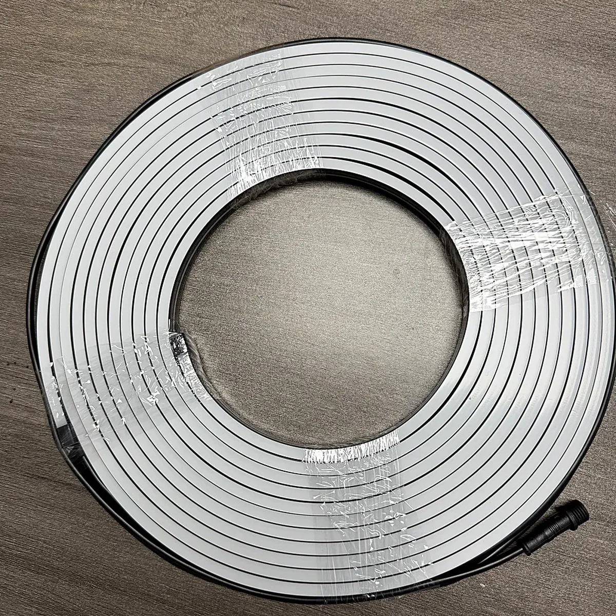
Then cut once, square. What works is a sharp blade against a square edge — a set square, a mitre block, or the dedicated neon cutting tool most neon suppliers sell alongside the profile — pressed through in a single stroke rather than sawed back and forth. You are cutting two very different materials at once: a soft face and a harder backing wall. Sawing loads the soft side more than the hard side and produces a face that is visibly angled even when the mark looks straight.
An angled or ragged cut costs you in three places, all of them expensive:
- The end cap will not seat. Push-on caps and their gaskets are dimensioned for a flat face. A cut a few degrees off leaves a crescent-shaped gap that no amount of adhesive fills reliably.
- The conductors arrive nicked. A sawed cut tears at the copper rather than shearing it, which is how a run that tests fine on the bench develops an intermittent fault after a season of thermal cycling.
- The face smears. Silicone cuts cleanly but deforms if you drag the blade; deformed material curls over the conductor pads and blocks both the adhesive and the solder.
Field rule: if the face is not flat enough to seat an end cap, it is not a sealed end — it is a place where water will sit.
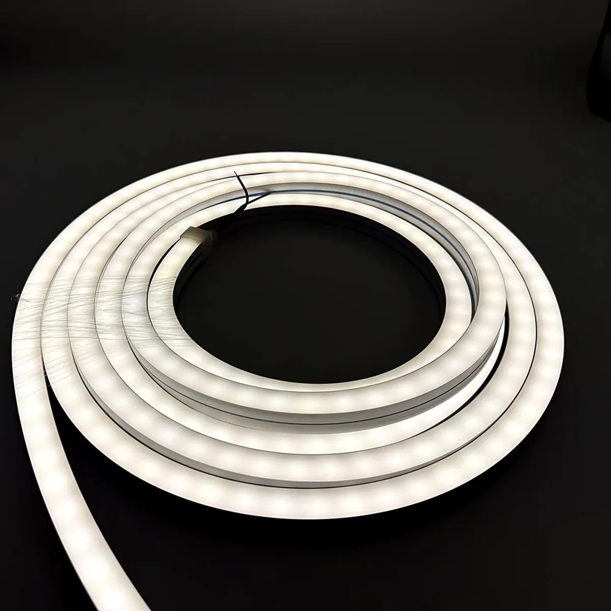
Check the face before you go further — and before you work out how to connect LED neon flex back into the run: the exposed copper pads should sit flush on the base, not pulled, not burred. Do not sand the end to tidy it; rounding the silicone edge is exactly what stops the cap sealing.
If you cut in the wrong place, do not invent a joint in the middle of the extrusion. Cut the damaged section away at the nearest cut marks on both sides and re-terminate. A proper end cap at a proper cut point beats a spliced joint buried inside a sealed profile — repairing a mid-run break inside an extrusion is a factory operation with potting and a pressure test behind it; on site it produces a joint you cannot inspect, at a place you already know is prone to failure. That single rule closes the signage and channel letter lighting selection guide loop: choose products whose cut pitch matches your cut list, so you never need the joint you cannot build.
Silicone or PVC decides how you seal it
How to cut LED neon flex and how to seal it are two halves of one decision, and the material of the extrusion — not the brand on the box — decides which sealing chemistry will hold. This is the step that gets skipped online, and it decides whether your end cap is still attached in two years.
Silicone LED neon flex is a thermoset. It is crosslinked, so it does not melt and cannot be solvent-welded — nothing dissolves its surface to grip it. What bonds to silicone is silicone: a one-part silicone sealant that cures at room temperature. Choose a neutral-cure type rather than an acetoxy one, because the acetic-acid cure is aggressive toward the copper and the solder pads sitting a few millimetres away inside that joint. In exchange you get what makes silicone the default for outdoor signage: it stays flexible at low temperature, resists UV and ozone without chalking, and does not take a permanent set when the letter flexes in the wind. Superglue is not a substitute — cyanoacrylate bonds silicone poorly and cures rigid, so it fails at the first thermal cycle.
PVC neon flex is a thermoplastic. It can be joined with solvent cement — the cement softens the surface and the two parts weld into one — and it takes a wider range of adhesives. Its weaknesses mirror silicone's: it is stiffer, so it delaminates from the base at tight bends, and the plasticiser that keeps it flexible migrates out over time. Under UV the profile yellows and embrittles, which on a shader or a coloured sign is not only a mechanical problem but a colour one, because a yellowing jacket shifts the light passing through it. It is also far less forgiving of heat — which matters in the next section, because an iron temperature a silicone profile shrugs off will shrink PVC insulation back from the joint.
Silicone neon flex | PVC neon flex | |
|---|---|---|
Chemistry | Thermoset, crosslinked | Thermoplastic |
How the seal is made | Silicone sealant + push-on end cap; silicone-to-silicone bond | Solvent cement or PVC adhesive; welds the surface |
Adhesives that fail | Cyanoacrylate, epoxy, rigid hot-melt | Acid-cure silicone used on adjacent metal |
UV / weathering | Stable, no chalking | Yellows, embrittles, plasticiser migrates |
Heat tolerance at the joint | Handles soldering temperatures | Softens; insulation shrinks back |
Field verdict | Better suited to cut-and-reseal on site | Workable, mainly where the joint is protected |
One more physical fact belongs with the material: the direction the profile bends. Top-bend, side-bend and 360° profiles curve in different planes, and the plane decides where a cut end can physically hide — a top-bend profile has a flat backing that will sit into a routed groove, a 360° profile does not. Plan the joint to land where a housing or a service loop covers it, not where the profile happens to end. If you are choosing connector hardware rather than adhesive — gauge, pin count, ingress rating — that is a separate decision with its own criteria, and the pixel strip accessories guide covers the selection side of it. This article is about the joint you make with your hands.
Sealing the cut end: three ways, and when each one holds
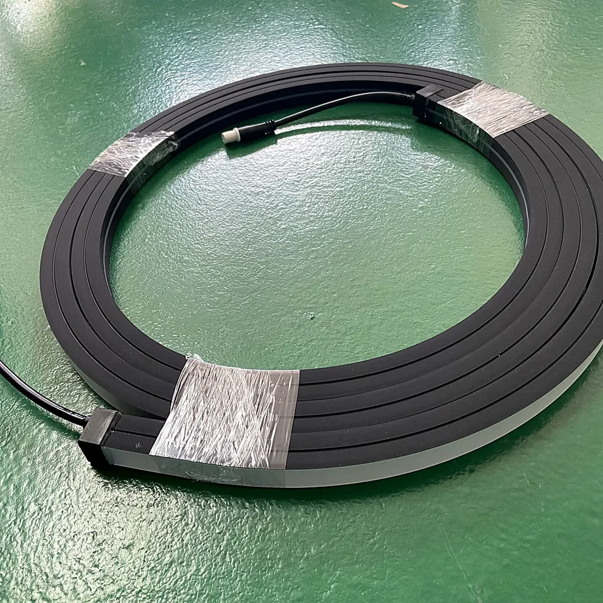
How to seal LED neon flex comes down to three methods, and between them they cover almost every site situation. Each has a failure mode worth knowing before you pick, because the failure mode is usually what decides the choice.
1. Silicone adhesive plus a push-on end cap. The default for silicone neon flex, and the method a supplier's own kit of neon flex end caps is designed around. It holds when the face is square, the adhesive is applied to both the inner wall of the cap and the cut face, and the cap is pressed until it bottoms out. It fails when the adhesive is applied only to the face — the cap then relies on friction against a smooth, low-energy silicone wall, and silicone is a material very little sticks to on purpose.
2. Potting the open end. Used where the profile is small or the end must be trimmed flush and no cap is available. A potting compound is poured into the open extrusion and left to cure, filling the volume around the pads. It holds where the compound is specified for the extrusion it is going into. It fails when a rigid compound is used in a flexible profile: the two have different coefficients of expansion, and thermal cycling eventually opens a hairline at the interface. Flexible, low-modulus compounds exist for exactly this reason; the tube of general-purpose epoxy does not.
3. Adhesive-lined heat-shrink tubing. A secondary seal, not the primary one, for joints that are exposed, walked on, or going into a groove that can hold water. The adhesive-lined heat-shrink tubing shrinks radially when heated and the inner adhesive layer melts and seals against the profile and the cable. It holds when the assembly is heated evenly and the tubing bridges the profile-to-cable transition. The common failure is partial shrinking: an incompletely shrunk end leaves a capillary path that pulls water straight into the joint.
The order of the work matters as much as the method:
- Cut square at a cut mark.
- True the face — one clean pass, no sanding, no rounding the silicone edge.
- Clean the face and the cap bore with isopropyl alcohol and let it flash off. Silicone releases a fine dust when cut, and nothing bonds through dust.
- Apply a neutral-cure silicone sealant to both surfaces — a thin, continuous bead with no voids at the corners, which is where leaks start.
- Seat the end cap and press it fully home, so it bottoms out against the profile rather than resting on the adhesive.
- Wipe the squeeze-out away while it is still wet. Cured squeeze-out cannot be removed without cutting into the profile.
- Leave it to cure, undisturbed. A one-part silicone sealant skins within tens of minutes and reaches full cure in about 24 hours at room temperature; the adhesive's own datasheet governs, and cold workshops lengthen it. Do not bend the joint, and do not run the section at full load to "see if it looks right" before it has cured.
That seventh step is the one that gets ignored under schedule pressure, and it is the cheapest to get right: an un-cured joint flexed into a letter is a joint that has already failed.
And one case where all three are the wrong answer. On mains-voltage neon flex at a storefront, in a facade, anywhere the joint will be exposed and unreachable afterwards, the correct decision is made at the order desk, not on site — order the length cut and sealed at the factory. Every method above produces a joint that is good, but it is not a joint tested as an assembly, and on mains voltage that difference carries a real cost. The alternative is a specification decision taken at the order desk, before the blade comes out — and the joint you never have to make is the one that cannot fail.
What a field cut does to the IP rating
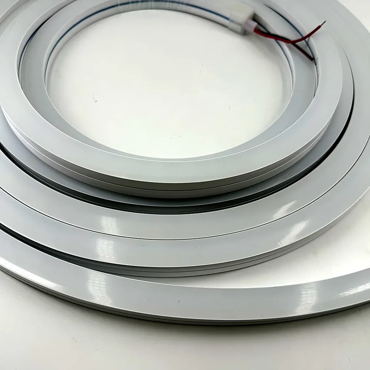
Here is the part almost no supplier states plainly. Almost none of the pages that rank for this topic explain how to reseal a cut end — one mentions waterproof glue and end caps in a single clause, and none gives the method, the cure time or the rating consequence. That silence is the interesting part: an IP rating is not a property of the material. It is a conclusion about one specific assembly.
The IP code carries two digits. The first is protection against solid objects and dust, running from 0 to 6. The second is protection against water, running from 0 to 8, plus the high-pressure jet case, 9. For a neon flex end going outdoors, the relevant water levels are:
Water digit | Meaning | What it takes in practice |
|---|---|---|
4 | Splashing water | Indoors only; not a storefront specification |
5 | Water jets from a nozzle | Rain on a sheltered shroud; jet direction still matters |
6 | Powerful water jets | Exposed signage, hosed down |
7 | Temporary immersion, 15 cm to 1 m, 30 minutes | Occasional wetting, not a drainage path |
8 | Continuous immersion under conditions the manufacturer specifies | The manufacturer's own test conditions define the limit |
The digits are defined in IEC 60529 and are verified by testing a finished item — a specific profile, a specific end cap, a specific adhesive, a specific amount of adhesive. Cut that item and the tested configuration no longer exists. A field joint can genuinely be watertight: use the manufacturer's end cap kit with the adhesive it was qualified with, cut the face square, keep the profile clean, and the joint will keep water out. What you cannot do is carry the original number across to it.
So the honest working rules for a cut-and-resealed end on a storefront are these:
- Treat the rating as belonging to the factory-terminated length. For anything that will be inspected, warranted or carried over to the next building, specify factory-sealed lengths and put the cuts where the tested configuration survives.
- Match the product to the location, then reseal. An LED neon flex IP68 build has more margin in the same field joint than an IP65 one, so specify above the location's requirement and let the joint work inside that margin instead of needing to be perfect.
- Never put the joint at the low point of a groove. Water does not need a hole; it needs a path and gravity. A joint at the bottom of a routed channel that drains into it will take water whatever its adhesive is, which is why the mounting geometry is part of the sealing decision, not a separate trade.
- Do not relabel the finished installation with the factory figure. "Resealed to the same method as the factory end" is a claim you can defend. Writing IP68 on a field build is a claim about work nobody tested.
That distinction — what the number certifies versus what your joint achieves — is what what IP67 and IP68 actually survive works through. This article stays with the cut end; the acceptance side of the number belongs there.
Reconnecting the run: solder or connector
Once the end is sealed you still have to get power and data back into the remaining length, and the choice of joint affects both.
Solder first, if the joint will be sealed and inaccessible. A correctly made solder joint is a fused connection, not a mechanical one; it does not loosen with vibration the way a friction connector can, and it does not rely on an elastomer that ages. The work is tinning both sides, keeping heat local, and letting the joint cool without moving it — a cold joint can look joined and still be unreliable.
Two things about heat and neon flex are worth knowing before the iron comes out. Silicone insulation tolerates soldering temperatures easily; PVC does not — it softens and shrinks back, which both opens the gap you are trying to close and leaves the joint mechanically unsupported. And inside a neon flex you are working in a confined volume: hold the profile so heat cannot travel along the copper into the LED pads behind it, or you will reflow a connection you never intended to touch.
Use a plug connector where the joint stays accessible. Connectors are the reason a cuttable run is reconfigurable in the field, and their outdoor failure mode is worth being explicit about: many are water-resistant rather than submersible, and their sealing depends on an O-ring or gasket compressing exactly as designed. A connector sitting in a wet groove where the O-ring cannot drain will pass water at the seal, not at the contacts — which is why the fault shows up at the far end of the run rather than at the joint.
And if the product is addressable, recheck the data chain, not just the power. This is the mechanism behind a failure the forums document but rarely explain: cut between the marks and the cut takes the last LEDs of a group with it, so every pixel after the cut shifts back by however many you removed and the surviving groups no longer line up with the mapping. The run still lights. The pattern is simply wrong from the cut onwards, and on video-mapped content that offset is a visible seam rather than a subtle one. Cut on the marks and the group boundary survives, so the mapping survives with it; cut between them and you will need to re-map the section in the controller — which means the cut list and the IC grouping in the addressable WS2811 neon flex have to be settled before anyone measures anything.

Keep power and data as separate concerns when you test. A run with a good data chain and an undersized feed lights perfectly on the bench and drops to a different colour at the far end once it is in place.
Prove the joint before it goes into the groove
The last step is the one with no do-over. Once a joint is inside a routed groove, a channel letter cavity that has been closed, or an aluminium channel behind a facade panel, fixing it costs a return visit and a removal — an order of magnitude more than the ten minutes you are about to spend.
Test in this order, before anything is fixed:
- Data chain first, dry. Power on with the run visible, and confirm the whole length responds and the pattern runs to the end without a break. A data fault found here costs a re-solder.
- Full load, real conditions. Run the section at the load it will carry, at the ambient temperature it will see. Colour and brightness that look right on a bench at 20 °C can shift when the same section is warm, and warm is where voltage drop stops being theoretical.
- Length against feed, before you seal anything. A single-ended feed that is inside the length limit on paper can still be outside it once connector losses and the actual supply voltage are included. If the far end is visibly dimmer or warmer in colour, the fix is a second feed point, not a different product. LED voltage drop covers the calculation and where to place the injection points.
- Seal, cure, then re-inspect the joint only. Do not re-flex a cured joint to check it. Look at it: a continuous adhesive fillet, a cap that has bottomed out, no gap at the corners.
- Walk the sequence with a checklist. It is a short list, and it is the kind of list that gets skipped on the fourth sign of the day. The pre power-on commissioning checklist is built for exactly that moment.
For channel-letter work, add one planning rule that saves the most time across a whole job: design the cut list so that every cut lands on a mark and every cut end lands inside an accessible letter cavity or a service loop. Letters assembled off site end up with their cuts either already made and sealed at the factory, or still to be made on site with a cavity to make them in. What you want to avoid is the third case — a cut end that exists only because a straight run was a few centimetres too long, buried in the middle of an inaccessible section. At storefront scale that list stops being a note on the back of a hand and becomes a document: a delivered US bar facade that used 2,600 m of pixel strip and neon flex (the 2,600 m US bar facade) is the scale at which planning the cuts pays for itself.

Two questions to ask before you buy cuttable neon flex
Cutting LED neon flex on site reduces to two questions you can ask any supplier, including us, before an order goes out:
- What is the cut interval for this profile and this IC? Not "is it cuttable" — cuttable is a yes/no, and it is the least useful answer available.
- What end cap and what adhesive do you supply for it? A product sold for field cutting without a matching end cap and a specified adhesive has pushed the hardest part of the job back onto the installer.
Where both answers exist, a cut-and-reseal on site is a normal part of the job. Where either is missing, the honest move is to order the length factory-sealed instead. A silicone end cap, LED neon flex profile and a specified adhesive are a matched set: the adhesive is qualified against that cap and that extrusion, so buy the three from one source.
PILEDS builds neon flex in 8 models from 12 × 06 mm up to 40 mm 360°, at densities from 30 to 240 LED/m, with the IC, voltage and ingress class specified per order. For mains-voltage and facade work it is usually the better answer to have us ship the run cut to length with the ends sealed and QC'd on our own line before it leaves. If you are specifying a signage run and want the cut intervals for a particular profile, ask our engineers and we will give you the numbers for the model you are actually buying.
Specifying pixel LED for a real project?
Send the spec — pitch, IC, IP class, run length, voltage — and you get an engineer's answer, not a catalogue. Samples and OEM/ODM quotes from the Shenzhen factory floor.