
SPI vs PWM vs DMX: How Pixel LEDs Are Driven
SPI vs PWM is not a real choice: PWM sets brightness inside each pixel, SPI carries the data, DMX handles addressing. Here is which layer decides your project.
Most "SPI vs PWM" comparisons are answering a question nobody asked. They put two words side by side in a table, score them on speed and distance, and declare a winner. Then an integrator reads the table, orders a strip, and discovers on site that the two terms were never the same kind of thing.
Here is the part that matters before you spec anything: PWM is how a pixel decides how bright to be. SPI is how it learns what colour to be. DMX512 is how a controller addresses a group of fixtures across a whole installation. One is inside the driver chip, one is a wire between chips, one is a network above them.
SPI vs PWM Is Not a Choice Between Equals
Strip away the marketing and a pixel LED installation has three questions to answer, in this order:
- Where does the brightness come from? Every addressable LED — WS2811, WS2812B, WS2815, SK6812, UCS1903, all of them — produces intermediate brightness by switching its internal constant-current driver on and off very fast. That is PWM, and it happens inside the chip whether or not you ever think about it.
- How does each pixel learn its own colour? On an SPI-class strip, a serial data line hands each driver a 24-bit value (8 bits red, 8 green, 8 blue) and the driver forwards everything after its own three bytes to the next one down the line.
- How does the control desk talk to hundreds of those strips at once? This is where DMX512 lives — a 512-channel frame addressed to fixtures and decoders, usually carried over RS-485.
So the honest comparison is SPI vs DMX, because those two occupy the same layer and you genuinely pick one. PWM is not the rival of either. It is the mechanism that turns a digital value into light, and it is present in both architectures.
Layer | What it decides | Where it lives | What you actually choose there |
|---|---|---|---|
PWM | Brightness of one pixel | Inside the driver IC | IC family, PWM frequency, bit depth |
SPI | Which pixel gets which colour | Data line between drivers | Strip IC family, 3-wire or 4-wire |
DMX512 | Which fixture gets which channels | The control network above the strip | Universe plan, decoder, address map |
Chip-level detail — how WS, SK, TM and UCS parts differ in addressing, colour depth and failure behaviour — is in the addressable LED driver IC comparison. This article stays one level up, at the system.
PWM: How a Pixel Decides Its Brightness
An LED is not a dimmable resistor: drive it at half voltage and you get a colour shift, not half brightness. So driver chips never vary voltage. They switch the LED fully on and fully off, thousands of times a second, and let your eye average the result. The fraction of each cycle spent in the "on" state is the duty cycle, and duty cycle is brightness. Pulse-width modulation is the general name for that technique.
Three properties matter here:
PWM frequency decides whether cameras see it. A strip dimmed to 10% on a 400 Hz PWM is off for 90% of every 2.5 ms cycle. Your eye integrates that into a smooth dim. A camera with a 1/1000 s shutter does not — it catches the dark window and records a band or a flicker the audience never sees. Broadcast, touring and anything that will be filmed want the off-window short enough to hide inside a single frame: low kilohertz, not hundreds of hertz.
Bit depth decides how smooth the dim is. With 8 bits per channel you get 256 steps. On a long fade from full to black, the bottom of that curve — where the eye is most sensitive — collapses into a handful of visible steps. Some IC families claim a higher internal PWM resolution than the 8 bits per channel the data link actually carries, the extra steps being generated between received frames; check the datasheet rather than the product summary, because the methods differ.
PWM is invisible to your control protocol. Nothing in a DMX frame or an SPI packet says "use 400 Hz". The controller sends a value; the driver decides how to render it. Two strips that answer to the same controller can flicker completely differently on camera because their driver ICs run different PWM engines.
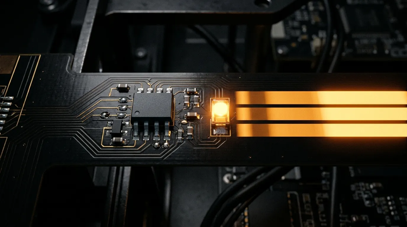
Three brightness levels from the same LED: progressively shorter on-time inside each switching cycle delivers progressively less averaged light, and the driver IC is doing this thousands of times a second.
SPI: How the Address and Colour Reach Each Pixel
SPI here means the single-wire (and clocked two-wire) serial links that addressable strips use — not the four-wire SPI peripheral in a microcontroller, though the idea is related. The working principle on a WS2811-class strip is a daisy chain: the controller sends one long bitstream, each driver takes the first 24 bits it sees, latches them as its own colour, and re-transmits the remainder to the next driver.
The WS2812B datasheet gives the numbers that make this concrete: 24 bits per pixel, transmitted at 800 kbit/s, which works out to 30 µs per pixel. The order on the wire is GRB, not RGB — worth knowing before anyone writes the first line of driver code and spends an evening swapping red and green panels. Every pixel in the run passes the data along, so the last pixel waits for every pixel before it. That single fact drives most of the engineering decisions downstream — refresh rate, maximum pixels per port, and why a broken pixel in the middle of a single-signal run takes the rest of the strip dark.
Two variants change the economics:
- Clocked links such as APA102 and SK9822 add a separate clock line. The receiver no longer has to recover timing from the data itself, so the link can be clocked far faster than the 800 kbit/s of the single-wire family. The cost is a fourth conductor and a controller that supports it.
- Backup-data parts such as WS2813 and WS2815 carry a second data line. If one pixel dies, the signal bypasses it instead of stopping there. The difference between these two parts — voltage, standby current, wiring — is covered in WS2815 and WS2812B compared.
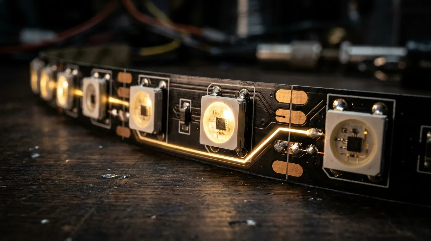
One data trace, one direction. Each package reads its own 24 bits and regenerates the rest of the stream for the pixel after it.
If the physical build of these strips is new to you, what an SPI LED strip is covers the cut points, voltage options and IC placement before you get to protocol questions.
DMX512: The Layer Above — Universes and Addressing
DMX512 answers a different question: how do you address a large number of independently controlled outputs from one desk, over cable runs measured in tens or hundreds of metres? The standard defines 512 channels per universe, carried as a continuous frame over an RS-485 differential pair at 250 kbit/s, with up to 32 unit loads on a daisy chain and a 120 Ω terminator at the far end. You can read the normative definition in ANSI E1.11, the DMX512-A standard.
Two consequences follow.
Channel budget is unforgiving. 512 channels sounds generous until you convert it. At 8 bits per channel, one universe addresses 170 RGB pixels, or 128 RGBW pixels. A 1,000-pixel facade needs six universes before you have drawn a single fixture on the plot. That is why large pixel jobs are planned in universes from the start, not counted in strips.
DMX does not drive a pixel strip directly. A DMX frame contains channel values, not pixel bitstreams. Something has to translate: either fixtures with a DMX receiver built in, or a DMX-to-SPI decoder that takes a block of channels and re-emits them as an SPI stream to the strip. That decoder is the seam between the two layers, and it is where most integration mistakes happen — the decoder's pixel capacity per output, its channel mapping and its refresh behaviour all have to match what the desk is sending.
Art-Net and sACN carry those universes over Ethernet; DMX512 against Art-Net covers when that layer earns its complexity.
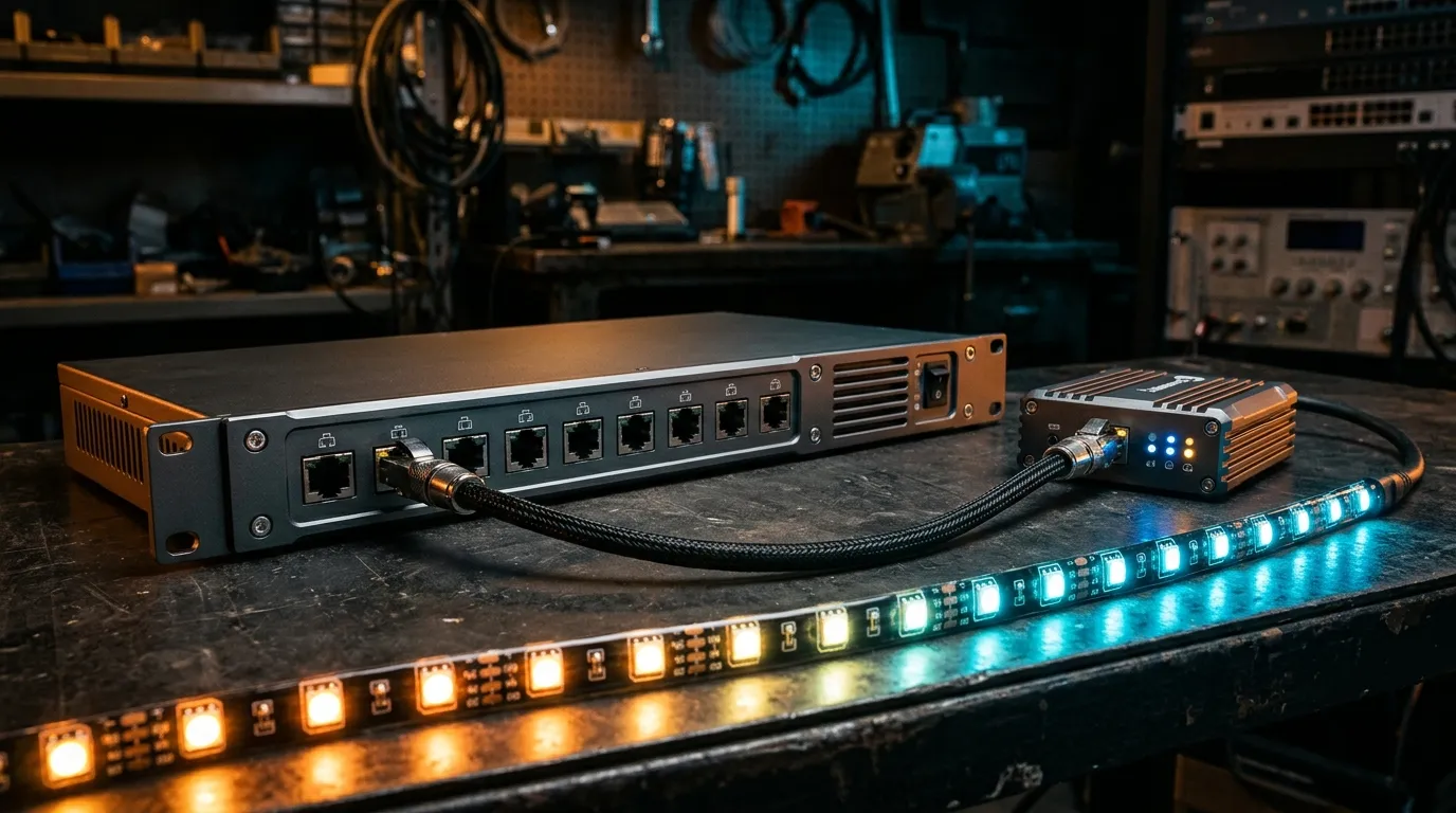
The seam in practice: universes arrive on the network ports, a decoder converts a channel block into an SPI stream, and the strip only ever sees SPI.
SPI vs DMX: The Differences That Decide a Project
Now the comparison that actually is a comparison. Both can deliver per-pixel colour; they differ in what they cost you to run.
SPI (addressable strip) | DMX512 | |
|---|---|---|
Physical layer | Single-ended data line, 3-wire or 4-wire | RS-485 differential pair, shielded |
Practical run before help | A few metres; repeaters or re-clocking beyond that | Hundreds of metres per universe |
Addressing overhead | 24 bits per pixel, passed down the line | 3 channels per pixel (RGB), 4 for RGBW |
Per-controller capacity | Pixels per output port, set by the controller | 512 channels per universe, 32 unit loads per chain |
Typical failure signature | One dead pixel can blank the rest of a single-signal run | A bad node or missing terminator degrades the whole chain |
The DMX column is not an opinion: 512 channels per universe and 32 unit loads per chain are the DMX512 addressing model, and what they limit is how many pixels fit in a universe — not whether pixel-level control is possible. A DMX-to-SPI decoder maps three consecutive channels onto one pixel, which is exactly how the 170-pixel figure above is produced.
The pattern behind the table is simple: SPI gives you point-level control at short range; DMX gives you long range at the cost of three channels for every pixel. Neither is more "stable" in the abstract — the stability question only becomes meaningful once you know the run length, the pixel count and whether the strip is indoors behind a diffuser or on a facade in the rain.
In practice most large installations use both, in series: DMX or Art-Net from the desk to the rack, decoders in the rack, SPI from each decoder output to the strip. The choice you are really making is where that boundary sits — at the fixture, at the rack, or at the pixel.
Where PWM and SPI Do Compete: Analog Strip vs Pixel Strip
There is one place where PWM and SPI genuinely compete, and it is not inside a pixel strip — it is at the fixture level.
A constant-voltage RGB strip with no addressable IC has every LED on the run showing the same colour at the same time. You dim it with a PWM dimmer that switches the whole run, and you change colour by balancing three PWM channels. It is cheap, simple, and completely adequate for cove lighting, a sign box or a facade wash where the surface is meant to read as one colour.
An SPI pixel strip inverts that: every pixel carries its own driver, so a chase, a gradient or video content becomes possible. The price is a decoder, a shorter data run, and a controller that speaks the pixel protocol.
Analog strip + PWM dimmer | SPI pixel strip | |
|---|---|---|
Control resolution | Whole run, one colour at a time | Individual pixel |
What reaches the strip | Three PWM dimming channels | A serial pixel bitstream |
Typical use | Cove, sign box, facade wash | Chase, gradient, video |
The rule of thumb is worth stating plainly. If the whole run should be one colour at any given moment, an analog strip plus a PWM dimmer is the cheaper and more robust answer. If any part of the run has to differ from its neighbour, you need addressable pixels — and then the remaining question is SPI or DMX.
Four Numbers to Check Before You Specify
Most protocol mistakes are arithmetic mistakes made late. Run these four checks before the purchase order, not after the first site visit.
1. Refresh rate against pixel count. At 800 kbit/s and 24 bits per pixel, each pixel costs 30 µs. A port driving 512 pixels needs 15.4 ms per frame, which caps you at about 65 frames per second. At 1,000 pixels you are at 30 ms and roughly 33 fps; at 2,000 pixels, 17 fps. If the content is a slow colour fade, 17 fps is fine. If it is a fast chase timed to music, it is visibly wrong. Adafruit's NeoPixel guide documents the same per-pixel timing from the controller side.
One correction is needed before you treat 65 fps as the end-to-end figure. A full DMX universe takes about 22.6 ms to transmit at 250 kbit/s, so anything fed from DMX through a decoder refreshes at roughly 44 Hz at best. Your end-to-end rate is the lower of the SPI port's frame rate and that ceiling — and once a universe is full, adding pixels by splitting them across decoders does not raise it.
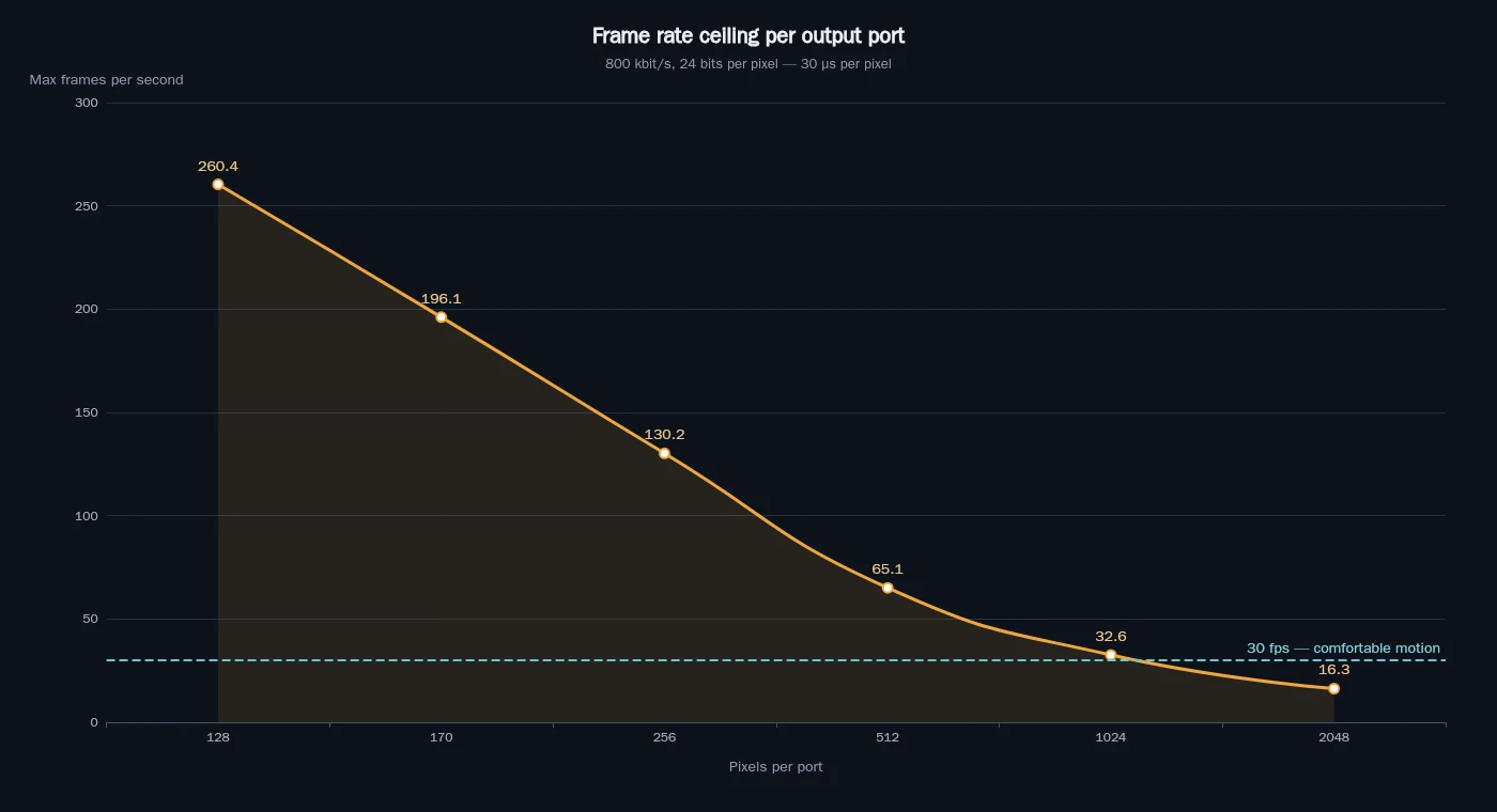
The same arithmetic as a curve: the frame rate you can actually deliver drops as pixels are added to a port. Below roughly 30 fps, motion starts to look stepped rather than smooth.
2. Channel budget against pixel count. 512 channels ÷ 3 = 170 RGB pixels per universe. If your decoders are 4-channel RGBW, it is 128. Round down, never up, and remember that any channel you spend on dimmer or strobe control comes out of the pixel budget.
3. Pixels per port against strip length. Controllers are specified by pixels per output, not by metres. A 16-pixel-per-metre strip on a 5 m run is 80 pixels — trivial. The same strip over 30 m is 480 pixels, close to the ceiling of a 512-pixel port, and it needs power injection long before it needs a protocol change. The controller capacity calculator does that arithmetic per port before you commit to a strip length.
4. Distance against cable type. SPI over a few metres of unshielded wire next to mains cable is where "random flashing" comes from. DMX over 300 m of the wrong cable with no terminator produces the same symptom for a different reason. When the run is longer than the architecture wants, the answer is a decoder closer to the strip, not a thicker data cable.
What Goes Wrong on Site, and Which Layer to Check First
Symptoms map to layers. Working down this list saves days of swapping hardware.
Symptom | Most likely layer | Check first |
|---|---|---|
Random flashing, wrong colours mid-run | Data integrity | Data line length, shielding, common ground, level matching |
Whole tail of a run goes dark | SPI chain | The first dark pixel; single-signal vs backup-data part |
Colour drifts warm or dim toward the end | Power | Voltage drop, injection points, conductor size |
Visible banding on camera, fine to the eye | PWM | Driver PWM frequency and dimming depth |
Nothing responds at all | Address / mapping | DMX start address, universe, decoder channel map |
Two entries are routinely misdiagnosed. Level mismatch — a 3.3 V logic controller feeding a 5 V strip — sits in the data layer and presents as intermittent, distance-dependent failure, so it gets blamed on cable. And colour drift toward the end of a run is almost never a protocol problem at all; it is voltage drop over long runs, and no amount of re-addressing fixes it.
How to Write It on a Purchase Order
A specification that survives procurement looks like one line of constraints, not a paragraph of adjectives:
Addressable pixel strip, 60 px/m, WS2815, DC12V, IP67, 5 m per reel, 4-pin backup-data wiring, driven by DMX-to-SPI decoders at 1,024 pixels per output.
Six fields do most of the work: protocol at each layer, driver IC, voltage, pixel density, IP rating, and pixels per output port. Add the wiring convention and the connector type, and you have removed the three ambiguities behind most re-orders: which IC, how it is addressed, and what it plugs into.
Where the strip and the controller come from the same factory — as they do in our own range — that line can be quoted against a matched pair rather than assembled from two catalogues. The Art-Net, DMX and SPI controllers in that range include DMX-to-SPI decoders rated at 1,024 pixels per output. Whether you buy them together or separately, specify them together: the decoder's per-output pixel capacity and the strip's IC family have to agree, and that agreement is a number, not a promise.
FAQ
Does PWM work with LEDs?
Yes — for addressable pixels it is unavoidable. The LED switches fully on and off at a fixed frequency, and duty cycle sets apparent brightness. It is the standard method inside every pixel driver IC.
What is the SPI lighting protocol?
SPI in pixel lighting means a serial data link from a controller to a chain of driver ICs. Each IC takes its own 24 bits — 8 per colour channel — and forwards the rest. Clocked variants add a separate clock line; single-wire variants such as WS2811 run at a fixed data rate instead.
Which is better, PWM or DC dimming?
They answer different questions. PWM switches the LED at full current and varies the on-time; DC dimming varies the current itself. In a pixel strip the driver IC fixes the method, so you are choosing a chip, not a dimming philosophy — compare PWM frequency and bit depth instead.
What is PWM and why is it used?
Pulse-width modulation varies the average power delivered to a load by switching it on and off rapidly and changing the proportion of on-time. It suits LEDs because it dims without shifting the colour point, which varying the voltage would do.
If you are choosing between protocols for a specific installation, the useful inputs are the pixel count, the longest run, the frame rate the content needs and the environment. Everything else follows from those four numbers.
If you would rather have that arithmetic checked before you commit, send us those four inputs and we will size the decoders and the strip against each other and quote them as one line.
Specifying pixel LED for a real project?
Send the spec — pitch, IC, IP class, run length, voltage — and you get an engineer's answer, not a catalogue. Samples and OEM/ODM quotes from the Shenzhen factory floor.