
WS2815 vs WS2812B: Backup Data Line Worth It?
WS2815 vs WS2812B: the 12 V rail cuts power-injection points and the second data line survives a dead pixel. What each buys, with datasheet conditions.
Short version: the backup data line is worth its premium in one specific situation — when a single failed pixel would take out everything downstream of it, and getting to that strip to replace one pixel is expensive. Both chips run the same 800 kbps, 8-bit-per-channel NZR protocol, so this is not a choice between good pixels and bad pixels. WS2815 moves the rail to 12 V (fewer power-injection points, less current per metre) and adds a second data conductor that keeps the run alive past a dead pixel. WS2812B stays at 5 V, draws less power on saturated colour content, costs less per metre and has the wider ecosystem. Spec a 12 V WS2815 run when the installation is permanent and hard to reach. Spec WS2812B when the run is short, serviceable, or the job is pure effects on a budget.
This is from PILEDS, and it comes with a disclosure: we build addressable strip on both chips, so we have no stake in which one you buy — only in the run still working after it leaves the bench. Every number below is traced to a WorldSemi datasheet or to a named third-party test, with its conditions attached. Where the sources disagree with each other, we say so rather than quoting the flattering figure.
WS2815 vs WS2812B: the two chips, side by side
Strip the marketing off both parts and there are exactly two hardware differences that change what you can build: the supply rail, and the number of data conductors. Ask the question in either order — WS2815 vs WS2812B or WS2812B vs WS2815 — and it comes down to those two, because everything else — the protocol, the colour depth, the package — is shared. That is why the two get sold interchangeably, and why "is WS2815 just a 12 V WS2812B?" is the first question people ask.
Mostly yes, and that framing is more useful than the shelf-talk about one being an upgrade. The WS2812B datasheet and the WS2815 datasheet are both published by WorldSemi, and they describe the same signalling:
The spec table, with sources named
WS2812B | WS2815 | |
|---|---|---|
Supply voltage (absolute max) | 3.5 – 5.3 V | 9.5 – 13.5 V |
Nominal rail | 5 V | 12 V |
Data conductors | 1 (DIN → DOUT) | 2 (DIN plus BIN backup) |
Data rate | 800 kbps | 800 kbps |
Colour depth | 8 bit per channel, 256 levels, 16,777,216 colours | same |
Refresh / scan frequency | not less than 400 Hz | 2 kHz |
Reset frame time | above 50 µs | above 280 µs |
Channel drive | not stated in the datasheet | constant current, 15 mA per channel |
Quiescent current | not stated in the datasheet | 2.1 mA |
Operating temperature | −25 to +80 °C | −25 to +85 °C |
Package | 5050 SMD | 5050 SMD |
The two differences that change what you can build
Both of those documents are third-party mirrors of the WorldSemi PDFs — the originals sit on the manufacturer's own site — so if a number matters to your design, pull the current revision from WorldSemi before you commit to it.
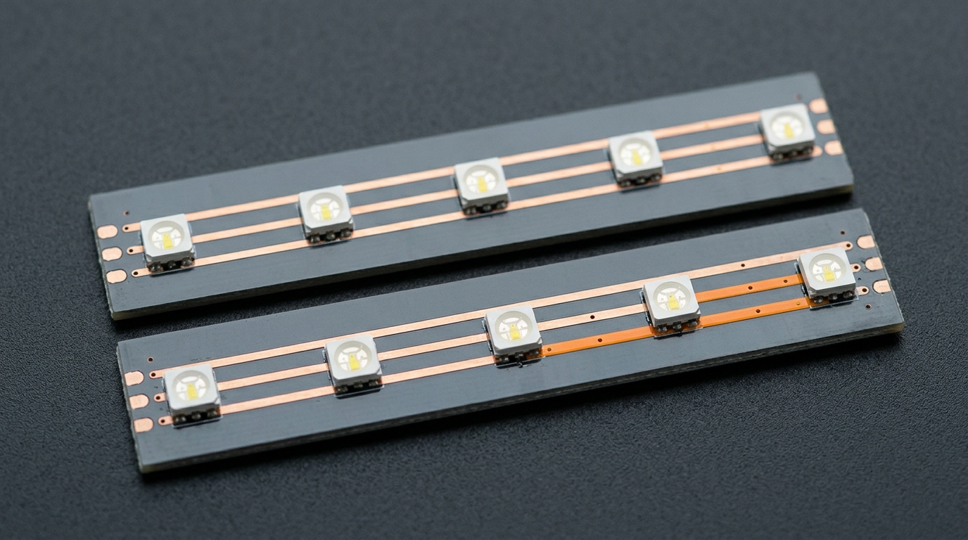
Two rows in that table are worth reading twice. The first is the data conductors: 5 V addressable strip carries power, ground and one data line; a WS2815 12 V LED strip run carries a fourth conductor that exists only to keep the signal moving when a pixel stops passing it on. The second is the reset time — 50 µs against 280 µs. That gap is why you cannot interleave the two parts in one chain, and we come back to it below.
If you are still choosing between driver families rather than between these two parts, the addressable driver IC guide lays the whole WS / SK / TM / UCS landscape out, and the WS2811 alternative frame covers the external-driver part of the same family.
A 12 V run needs a fourth conductor. It carries signal, not brightness — nothing about the extra wire makes the pixels brighter.
The 12 V rail on a real run
Current draw for the same run
The practical reason to move to 12 V has nothing to do with the LEDs and everything to do with copper. Take a 300-pixel run at full white and do the arithmetic both ways.
On 5 V, the sizing convention for addressable strip is 60 mA per pixel at full white — 0.3 W, from three channels at roughly 20 mA each. Treat that as a budget rather than a datasheet row: the WS2812B datasheet specifies its supply range and its logic thresholds but not a per-channel drive current, so the convention is what 5 V designs are still sized from, and it is deliberately conservative. Three hundred pixels is 18 A. On 12 V, the WS2815's own datasheet specifies a constant current of 15 mA per channel, so 45 mA per pixel and 13.5 A for the same run — a datasheet figure, not a convention.
Less current through the same copper means less voltage lost along it, which is the whole point: a 12 V run reaches further before the far end starts going pink, and it needs fewer power-injection points to get there. Injection points are not free — every one of them is a drill hole, a gland, a cable run and an item on a maintenance drawing. If your install is 20 metres of continuous strip, the difference between feeding it from three places and feeding it from six is a real line item, not a rounding error.
Sizing the feed
Two rules keep the sizing honest. First, work out current from your strip's rated watts per metre at full white, not from a number you read on a forum; current is the number that decides cable gauge and injection count, and it is the one most sheets leave out. Second, size the power supply with headroom above that figure rather than exactly at it — a supply asked to run flat out from day one is a supply that will fail on the hottest day of the project. The mechanics of both are worth reading properly: why voltage drop dims the far end and sizing the power supply for a pixel run.
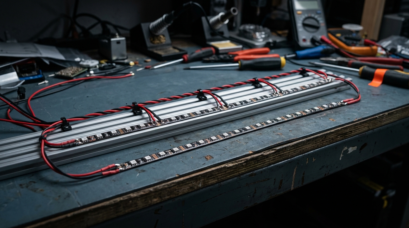
Same pixels, same length, different rail. The 12 V run needs fewer feed points because it moves the same power at a lower current.
What the 12 V rail costs you
What the measured power tables show
Here is where 12 V strip gets oversold. It is not automatically the more efficient option, and WS2815 power consumption depends entirely on what you are displaying.
QuinLED publishes a power-usage test table comparing these exact families in one place, and the write-up around it is the reference the LED community cites. Three rows of that table tell the story:
Test condition (QuinLED sheet v0.5: 300 LEDs total, WLED 0.9.1 on ESP8266, reading taken after 15 s) | WS2812B | WS2815 |
|---|---|---|
RGB white at 100 % | ≈ 65.0 W | ≈ 48.6 W |
RGB white at 50 % | ≈ 33.9 W | ≈ 27.0 W |
Full-brightness colour effect | ≈ 25.5 W | ≈ 50.0 W |
Read those rows together and the pattern is clear: at a bright, mixed-white state the 12 V part is the lighter load, and on a saturated colour effect it can draw roughly twice what the 5 V part draws. (The sheet writes its decimals with commas; 33,90 W is 33.9 W.) The same sheet carries notes that say the pattern plainly — a 12 V strip is "easier to wire, but will use more power", and the WS2815 "burn off power per LED when not full white, so is very inefficient". That is what burning off power means electrically: the channel is held at a fixed current and the voltage the LED does not use is dissipated in the driver. It is not a defect, it is the architecture — and it has a physical consequence, because that energy leaves as heat inside a profile or a sealed sleeve where it has nowhere to go.
These rows also let you check both per-pixel figures from the previous section, and neither one lands where the arithmetic would put it. Divide by 300: WS2812B at full RGB white measures 0.217 W per pixel against the 0.3 W the 60 mA convention predicts, and WS2815 measures 0.162 W per pixel against the 0.54 W implied by three channels at 15 mA on a 12 V rail. Both measured figures sit under the ceiling — which is what you would expect, since those channel-current specs are conservative maxima meant for sizing rather than predictions of running watts — but the two gaps are not the same size: roughly 1.4× on the 5 V part and roughly 3.3× on the 12 V part. We could not reconcile that difference from either source, and we are not going to quote whichever number flatters the argument. Size cable and supply from the datasheet ceiling, take running cost from a measurement, and let your supplier's full-white watts per metre settle the rest.
So: if your content is mostly saturated colour at high brightness, the 12 V premium buys you wiring convenience and costs you running power. If you are close to the supply's budget, measure your own content rather than assuming.
Why the numbers on forums disagree
This is also the point to say something about the numbers floating around on forums. Figures like "180 mW per pixel" or "0.162 W per LED" get quoted without the brightness, the colour state, the strip or the metre length they were measured over, and they contradict each other — one widely repeated forum post from 2019 asserts WS2815 is far less efficient with much higher heat dissipation, with no test conditions given at all, and the same forums circulate 0.162 W per pixel as if it were the chip's specification when it is a measured value under one specific strip and content. None of those numbers is wrong in the sense of being fabricated; they are unanchored. If you cannot say at what brightness a figure was taken, and on which strip, it does not belong in a specification.
The backup data line: what it actually protects
How the fallback works
Now the feature you are actually paying the premium for: the WS2815 backup data line. Each pixel has two data inputs — DIN and BIN — and the chip decides between them per pixel. Per the datasheet, the pixel latches its 24 bits and compares what arrived on DIN with what arrived on BIN; if DIN is silent, it switches to BIN and stays there until the strip is power-cycled. WorldSemi's own summary of the result is that "any pixel's failure won't affect signal transfer and total emitting effect".
In strip form an addressable LED backup data line shows up as a fourth terminal. ENTTEC describe it as a standard data line plus a backup data line, there so that data still carries down the strip if a pixel is damaged or removed — four terminals at the feed: 0 V, BI, DI, and supply. The WLED compatibility documentation lists the same thing in one line: WS2815, 12 V, has a backup data line.
Where the backup line stops helping
Two practical details decide whether the feature does anything in your build.
The first is that most controllers do not generate a backup stream at all. Your data output drives DI; BI has no natural partner, which is why so many installed runs leave it floating. The common field answer is to tie BI to ground, and to do it as close to the strip as the build allows: a long BI wire behaves as an antenna and injects noise into the signal that was supposed to be the reliable one. Terminate it at the strip, not back at the controller.
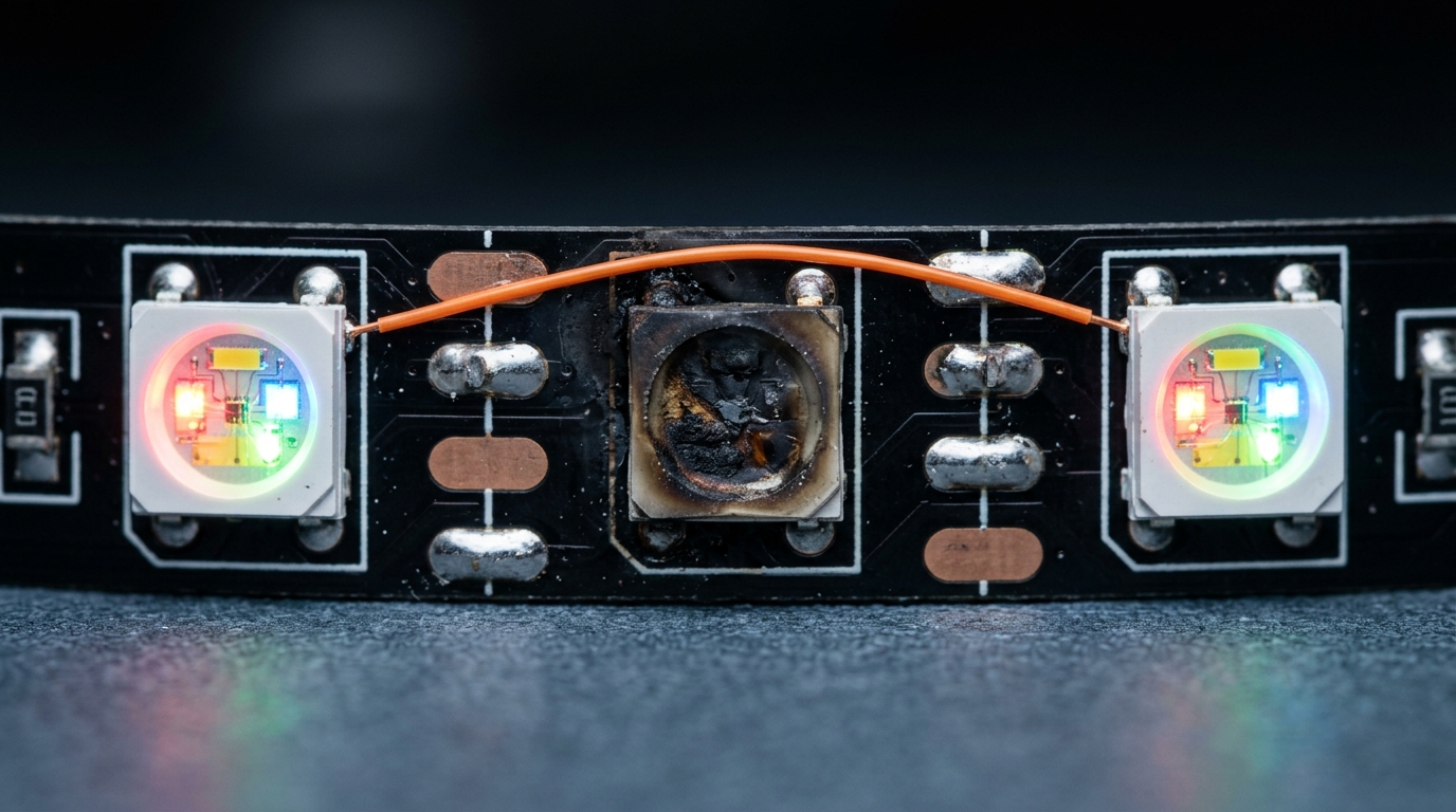
The second is what the backup line does not cover. It protects the data path. It does not protect the power rail, and it does not repair the pixel that failed — that pixel still goes dark, and you still have to replace it. What changes is the size of the blast radius: without the backup line, one dead driver takes out everything downstream of it, because each pixel has to regenerate and forward the stream. With it, the rest of the run keeps working while you arrange the visit.
The backup conductor bypasses a dead pixel's output. The dead pixel stays dark; the pixels after it do not.
When the backup line earns its premium
Turn the mechanism into a number and the decision stops being philosophical. The backup line is worth paying for when the cost of replacing one pixel exceeds the cost of the difference between the two chips across the whole run. That is a statement about access, not about the LED.
It earns its premium when all of the following are true:
- The run is permanent — facade, curtain wall, ceiling feature, tunnel, canopy, high-level signage. Work at height means a platform or a lift, and often a permit.
- The venue has operating hours that resist daytime access. Retail, hospitality and public buildings usually mean a night or Sunday window, priced accordingly.
- The strip is enclosed or embedded — in a profile, a sealed sleeve, or behind a diffuser — so a single-pixel repair is a partial disassembly, not a swap.
- A dark segment is visible and embarrassing. On a brand wall or a broadcast camera feed, "one pixel" is never the customer's description of the failure.
It does not earn its premium on a ground-level run you can reach with a ladder, a touring rig you rebuild weekly anyway, or a temporary installation with a known end date. Those are the same conditions where WS2812B gets cheaper and more efficient, and where a spare reel in the truck is better insurance than a redundancy feature built into the strip. Facade and curtain-wall work is the case that sits hardest on the "worth it" side, which is why the facade and curtain-wall guide treats serviceability as a design input rather than an afterthought.
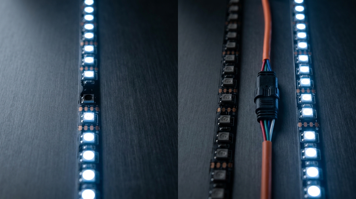
There is also a cheaper middle path worth pricing before you commit. Instead of paying for pixel-level redundancy, segment the run: give each 5–10 m section its own data feed and its own fused supply. A failure then costs you one segment instead of the whole install, at a fraction of the premium — but you are buying segment-level isolation, not pixel-level isolation, and everyone involved should know the difference up front. Choose the granularity you can afford and write it down.
Left: one dead pixel in a lit run — pixel-level isolation keeps the rest of the strip lit. Right: two separately fed sections meeting at a connector — segment-level isolation means a failure costs you one whole section. Both are valid; they are not the same purchase.
The data path is still the weak link
One thing 12 V does not fix: the data. The 12 V rail improves the power path, where higher voltage means lower current for the same watts. The data line is still a low-voltage single-ended signal running at 800 kbps, and it has its own rules.
Logic level
The first is logic level. Both parts specify their input thresholds against a 5 V rail — the WS2815 datasheet puts VIH at 0.7 × VDD, about 3.5 V — so a 3.3 V microcontroller output (an ESP32, a Raspberry Pi, most modern dev boards) sits below the guaranteed threshold. The standard guidance for both parts is to step the signal up before the first pixel, and WLED's hardware documentation goes further: it names the SN74AHCT125 as its recommended shifter and warns that the cheap bidirectional TXS0102/TXS0108 parts only hold up on data lines shorter than 50 cm. It often "works" without one on a bench at 20 °C with a short lead, and then misbehaves on site. This is the single most common 12 V installation fault we see reported, and no amount of copper on the power side compensates for it.
Distance and reset timing
The second is distance. Both datasheets put the single-ended reach at up to about 5 m — that is the stated limit, and it applies to the data line, not to power. Beyond about 5 m you are into differential transmission, a repeater or a shorter segment, regardless of whether the rail is 5 V or 12 V.
The third is the reason the two parts cannot share a chain. The data protocols are the same shape but not the same clock: WS2812B expects a reset low of above 50 µs, WS2815 requires above 280 µs. Feed a mixed chain and you will see the classic symptom of a reset frame being misread — the strip jumps, or the pattern shifts by a pixel and stays shifted. Keep a chain to one part number. WLED drives WS2815 as a standard three-wire stream, so your controller is rarely the constraint; a supported controller will do the job, and the WS2815B revision datasheet is worth checking if your supplier ships the B-V1 part, since its rated operating window is narrower than the original WS2815's.
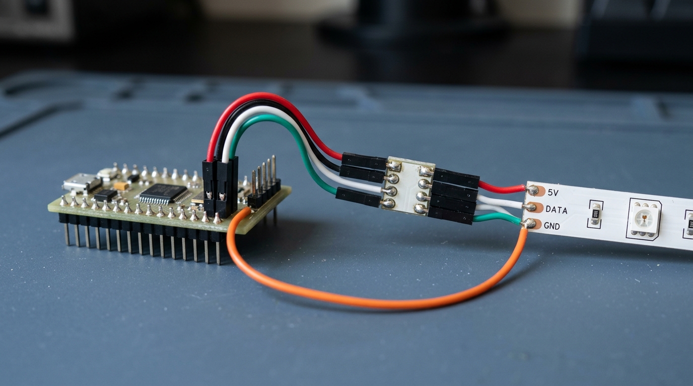
A level shifter between the controller and the first pixel, and BI tied to ground at the strip. Neither is optional in a permanent installation.
When to pick WS2812B instead
Plenty of projects should ignore this article's headline and buy the 5 V part. Reach for WS2812B when:
- The run is short and reachable. Under roughly 5–8 m at moderate brightness with one feed, the 12 V advantage largely disappears, and you keep the benefit of a 3-conductor build that any installer has done before.
- The content is saturated colour at high brightness. Per the measured table above, that is where the 12 V part gives up the most efficiency.
- Budget is the binding constraint, and the run is long. The per-metre gap multiplies by your length; at that point a segmented 5 V design with spare reels usually beats a pixel-redundant 12 V design.
- You want the widest possible choice of supplier, density and IP construction. The 5 V ecosystem is simply larger, and lead time on an unexpected variant is a real project risk.
- Your controller and supply already live in a 5 V domain. Keeping one rail avoids a second supply and the grounding questions that come with it.
Two honest by-products of this comparison. First, if you want a backup data line but do not want a 12 V rail, WS2813 exists — WLED lists it as a 5 V part with a backup data line; check availability and pricing against your project lengths before assuming it solves the problem. Second, if what you actually need is a proper white channel rather than redundancy, neither of these parts is the answer, and SK6812 versus WS2812B is the comparison to read instead.
Bottom line
Quick comparison, then the three routes:
Option | Rail | Failure behaviour | Best for | Cost profile |
|---|---|---|---|---|
WS2815 | 12 V | The run survives a dead pixel; the pixel itself still has to be replaced | Permanent, hard-to-reach, high-visibility runs | Higher per metre, fewer injection points, higher draw on saturated colour content |
WS2812B | 5 V | One failed driver blacks out the rest of the chain behind it | Short or serviceable runs, pure effects content, budget-bound projects | Lower per metre, but more injection points and more cable on a long run |
Pricing on both is quoted per project, so there is no list price to print here — the cost profile column is the usable comparison.
Three routes, and the first question is access, not price:
- Permanent install, hard to reach, failure is visible → WS2815 on 12 V, with BI terminated at the strip, a level shifter at the controller, and the injection plan drawn before the strip is cut.
- Short, serviceable run, or effects-heavy content, or a tight budget → WS2812B on 5 V, with spare reels and segmented feeds instead of pixel-level redundancy.
- You need a neutral white or a warm white as a base state → neither of these; go to RGBW.
If you are at the point of picking, the useful next step is not another opinion — it is your parameters. Our WS2815 addressable strip, 60 px/m is the 12 V part referenced here, and it can be configured for IP rating, colour and cut length for a specific run, with other densities available on request. Send us your run length, mounting height and content and we will tell you which rail we would quote, including the case where the answer is the cheaper one.
FAQ
What are the disadvantages of WS2812B LEDs?
The 5 V rail. It needs more current for the same power, so long runs need more power-injection points, thicker feed cable and a larger supply — and the far end of a long un-injected run shifts colour before it visibly dims. It also has no backup data line, so a single failed driver takes out everything downstream. Neither is a defect in the chip; both are consequences of running effects LEDs at 5 V.
What is the difference between WS2812B and WS2812?
They are the same protocol family from WorldSemi, and WS2812B is the version you will actually be quoted today. The practical differences are marginal for a new design; spec the part your supplier can deliver, and confirm the datasheet revision rather than the marketing name, because naming drift in this family is the norm.
What is the difference between WS2811 and WS2815 LED strips?
WS2811 is an external driver: one chip drives a small group of LEDs rather than one, which is why WS2811 strip comes in 3-LED cut units and costs less per metre. WS2815 is a single-pixel part with constant-current channels on a 12 V rail and a backup data line. If you need per-pixel addressability at low cost, that is the WS2811 trade; if you need per-pixel addressability plus a 12 V rail, that is WS2815.
Is SK6812 better than WS2812B?
Only if you need a white channel. SK6812 adds a dedicated white die, so white is neutral instead of mixed from red, green and blue, at the cost of a fourth channel and a higher price. For pure RGB effect content the extra channel is something you pay for and do not use.
Can I mix WS2812B and WS2815 in one chain?
No. They share the protocol shape but not the timing — the WS2812B reset floor is 50 µs, the WS2815 requires more than 280 µs — so a mixed chain can misread a reset frame and shift the pattern by a pixel. Keep each chain on one part number and treat the boundary as a data boundary even when the power supply is shared.
Specifying pixel LED for a real project?
Send the spec — pitch, IC, IP class, run length, voltage — and you get an engineer's answer, not a catalogue. Samples and OEM/ODM quotes from the Shenzhen factory floor.