
Curtain Wall Power Layout: Injection Points
Plan LED curtain wall power layout before you wire: voltage budget, load current per zone, injection point spacing, wire gauge, and a full 40 m worked example.
Every facade lighting project has the same quiet failure mode: the far end of the run is dim on opening night, the white pixels have gone yellow-pink, and someone is on a lift trying to figure out where the power should have gone. It is almost never a fixture problem. It is a curtain wall power layout that was improvised instead of calculated.
Power injection is the fix, and the question that decides everything is not whether to inject — it is where. On a curtain wall, where you place injection points is a calculation with three inputs: your voltage budget, your real load current, and how much current one injection point can carry. Work those three numbers and the injection points land at predictable distances. This guide runs the method top to bottom, then takes it to building scale — zones, distribution cabinets, and the outdoor-hardening details that DIY guides never mention.
The three numbers that decide every curtain wall power layout
Start with the physics, because it sets the budget. Every meter of strip draws current, and the copper in the strip traces and feeder cables has resistance. Voltage falls along the run — V = I × R, the physics behind voltage drop — and when it falls below the operating window of the driver ICs, you get the three classic symptoms: dimming at the far end, color shift (white goes yellow or pink first), and pixels resetting or flickering at full output.
The engineering target for permanent installs is to keep the total drop — feeder plus strip — under roughly 10% of system voltage. That is not a product guarantee, it is a design convention, and it gives you a hard number to plan against: at 24 V you have about 2.4 V of budget; at 48 V, about 4.8 V. Everything below hangs off that budget.
Three numbers then decide every injection point:
- System voltage — it sets how much current the run draws for a given wattage, and how much drop you can tolerate.
- Load current per meter — the fixture's real draw (watts per meter ÷ voltage = amps per meter).
- Current capacity per injection point — what one properly sized injection feed can deliver without cooking the connector or the PCB trace.
Count meters all day and you will get it wrong, because density varies: a 60 px/m strip draws several times the current of a 16 px/m pixel bar at the same brightness. Count amps instead, and the layout stops being a guess.
This guide is the power-layout deep dive inside our broader facade and curtain wall lighting coverage — where the design-side framework, IP decisions, and pixel pitch live. The facade lighting spec guide carries the safe-run table for each system voltage; here we go deeper on the injection math that table summarizes.
Step 1: Add up the real current
The load calculation is the part most people skip, and it is one line: watts per meter × length ÷ system voltage = amps per zone.
Take a typical mid-range facade pixel bar: 16 pixels per meter at 12 W/m. At 24 V that is 0.5 A per meter. A 40 m run is 20 A — which is why "run one long strip off one power supply" fails on facades. The current, not the meter count, is what decides how many feeds you need.
Two refinements matter before you trust the number:
- Calculate at the brightness you will actually run. Design content on facades rarely sits at full white. Many integrators size power at nominal white — roughly 50% output — and test at full white. The safe move is to calculate the worst case (full white) and note the nominal case; the injection layout must survive the worst case even if the show usually runs cooler.
- Respect the controller port limit. Each controller output has a current rating. A port rated for 5 A cannot feed a 20 A zone no matter how thick your cable is. The rule is one zone per port, or a port per injection group — this is also where a controller capacity calculator earns its keep when you are laying out ports, pixels, and current together.
A 40 m run at 20 A split into two 20 m zones gives you 10 A per zone — a number a standard 10 A-rated controller output or decoder channel can actually serve. That split is the whole trick of facade power layout: make the zones match what one port and one injection feed can deliver.
Step 2: Place injection points at the current limit
Power injection means running a fresh positive and negative pair from the power supply to points along the run, so no segment has to carry current for the whole facade. The data line is never touched — it passes through continuously; only the power rails are re-fed. That distinction — power injection is not data injection — is where most troubleshooting time gets wasted. On runs past roughly 100 m, budget for a signal buffer or distributed controller nodes: DMX/Art-Net distances and pixel-clock integrity have their own limits, separate from the power side.
The placement rule follows from the current math:
- Inject at both ends of any zone. A double-ended feed halves the worst-case distance any current has to travel, which roughly halves the drop contribution of the strip itself.
- Inject in the middle for runs past the safe length. Middle injection is the strongest tool for long runs because it splits the current in half in both directions. As a rule of thumb, a middle feed can carry roughly twice what an end feed can, since it only serves half the run.
- Never exceed the fixture's rated input current per injection point. For pixel bars and strips with 18–16 AWG tails, engineering practice is to keep a single injection point around 4–6 A and confirm the exact figure in the fixture datasheet. If a zone needs 10 A, use two injection points, not one overworked one.
The result is a spacing pattern you can draw on the elevation: for a 24 V bar drawing 0.5 A/m, a 10 A zone is 20 m; fed from both ends, each injection point carries 5 A — comfortable. Push the same fixture at 12 V and the same 20 m zone draws 20 A, needs four injection points, and the whole layout densifies. This is the hidden cost of low-voltage systems on curtain walls: more injection points, more junction boxes, more labor on the facade.
Rule of thumb: a 24 V bar at 0.5 A/m means a 10 A zone is 20 m — fed from both ends, each injection point carries 5 A, inside the 4–6 A comfort range for a properly sized feed.

On a real facade, every injection point is a junction box on the wall — which is why their spacing is a labor and maintenance decision as much as an electrical one.
Step 3: Size the feeder wire and protect the splices
The feeder cable to each injection point is part of the voltage budget — often the biggest part. The strip trace gets all the attention, but a long, thin feeder can eat your entire 10% before the power reaches the strip at all.
The practical table for copper feeders at the currents facade zones actually draw:
Feeder current | Up to 10 m (round trip 20 m) | Up to 20 m (round trip 40 m) |
|---|---|---|
5 A | 16 AWG | 14 AWG |
10 A | 14 AWG | 12 AWG |
15 A | 12 AWG | 10 AWG |
These are sizing starting points, not guarantees — the ~3–4% feeder-drop band assumes a ~48 V system; at 24 V, go one gauge up to stay in the same band. Distance, ambient temperature, and bundling all move the numbers. American wire gauge defines the sizes; when in doubt, go one gauge up, because undersized feeder is the most common hidden cause of "the strip is fine but the end is dim." Every injection leg should also be fused at the power supply — a fast-blow fuse sized just above the leg's design current protects the cable and the connector when something fails downstream.
The splices are where outdoor facades actually die. A sealed strip with an IP68 rating means nothing if its injection splice is bare twisted wire in the weather. Every injection connection belongs in an IP65–IP66 rated junction box (the IP code itself is defined in IEC 60529), with waterproof connectors or potted joints, and the box positioned where a technician can reach it from an access point. For the connector and enclosure side of the chain — power supplies, injection cables, waterproof joins — the power supplies and connectors guide covers the accessory family in detail.
Curtain wall power layout at building scale: zones, distribution, and access
Strip-level math gets you the injection spacing. Building scale adds a second layer: where the power supplies live and how the zones are fed. On a curtain wall, one giant supply room at ground level is usually the wrong answer — the feeder runs get absurd, and a fault takes down the whole facade.
The architecture that works on real high-rise projects:
- Zone the facade, then place a PSU per zone. Split the elevation into zones of roughly 20–40 m of run, each fed by its own power supply (or supply pair) located in a plant room, a floor distribution cabinet, or a weatherproof enclosure on a setback. Short feeders, independent failure domains, and commissioning one zone at a time.
- Keep a common ground across every PSU; never tie the positive rails together. Multiple supplies feeding one installation must share a common DC ground reference. The positive outputs, by contrast, must stay isolated from each other — tying two positive rails together lets current back-feed between supplies and can damage both. Professional pixel-control vendors make exactly this point in their power injection guidance, and it is the rule that separates permanent installations from hobby rigs.
- Put controllers next to their zones. Distributed Art-Net or DMX nodes near the injection zones keep data runs short and keep data zones aligned with power zones — the same split that made the power zones manageable also keeps each Art-Net and DMX controller output inside its current rating. For DMX-based systems, dmx pixel power injection follows the fixture's input rating, not the universe count.
- Plan access for every injection point. A junction box at 30 m up with no way to reach it is a maintenance dead end. Injection points belong at floor lines, balconies, maintenance catwalks, or wherever the facade's access system reaches — and that constraint should shape the zone boundaries before the wire is drawn.
- Add surge protection at the AC feed. Long outdoor low-voltage runs on a tall building collect induced surges from lightning activity in the area. A surge-protected feed per zone, at the PSU input, is cheap insurance compared with a dead controller after the first storm season.
- Plan for fire-rated cabling early. Where local codes require fire-rated (plenum) cabling or conduit on tall facades, factor that into the feeder path now — retrofitting flame-retardant cable after the zones are wired is far more expensive than speccing it from the start.

At building scale the power layout becomes a zone map: a PSU per zone, distribution cabinets at access points, and injection feeds sized to each zone's current.
This is not theoretical. Facade-scale systems at this density are delivered every year: an 86,500-pixel-point observation wheel in Singapore, 1,200 m of DMX wall washer on a German commercial plaza, 2,600 m of pixel and neon on a US bar facade — all running on the same zone-and-inject architecture described here. If you want the full project picture, the 86,500-pixel-point Singapore wheel case study shows how point-light and controller systems are structured at that scale.
Worked example: a 40 m pixel-bar facade zone
Put the whole method together. Assume a 40 m curtain wall zone of 16 px/m pixel bars at 24 V, drawing 12 W/m — typical mid-range facade bar values; replace them with your fixture's datasheet numbers.
- Load: 40 m × 12 W/m = 480 W. At 24 V: 480 ÷ 24 = 20 A total.
- Split into two 20 m sub-runs of 10 A each, matching a standard 10 A controller port per zone.
- Inject each 20 m sub-run from both ends: 10 A ÷ 2 = 5 A per injection point — inside the 4–6 A comfort range for a properly sized feed.
- Feeder wire: each leg runs up to ~10–15 m from the PSU. From the table above, a 5 A leg at that distance needs 14 AWG; at 15 m+, move to 12 AWG.
- Power supplies: 480 W × 1.2 headroom = 576 W. Two 300 W PSUs (one per sub-run) cover it with margin; Mean Well publishes sizing guidance for LED supplies if you want the 20% rule spelled out.
- Protection: fast-blow fuse per injection leg at the PSU (≈6 A for the 5 A design current), IP65+ junction box at every injection point, common ground across both PSUs, positive rails isolated.
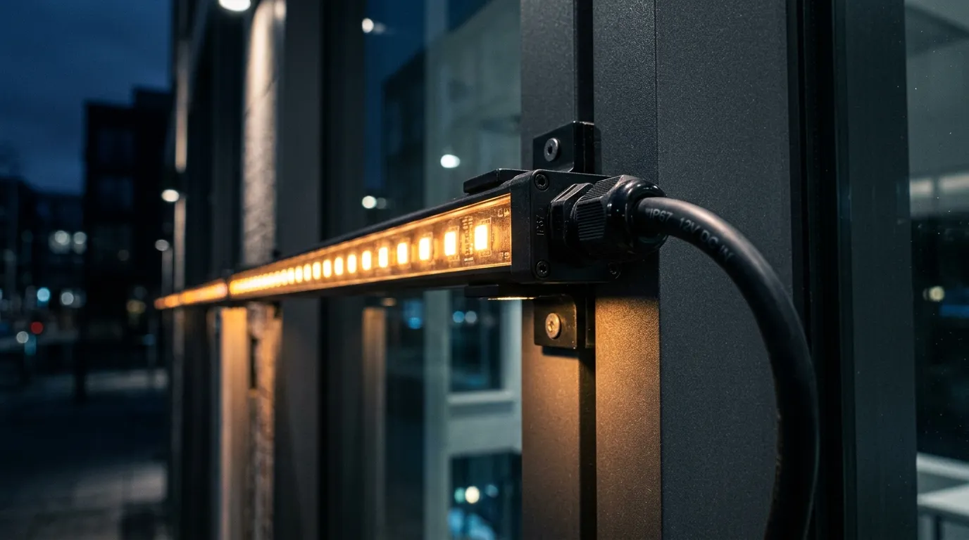
The physical injection point: a short, fused power leg entering the fixture through a waterproof connector — the detail that decides whether the joint survives its first storm.
Item | Value | How it was decided |
|---|---|---|
System voltage | 24 V | Budget: 2.4 V max drop; current halved vs 12 V |
Total load | 480 W / 20 A | 40 m × 12 W/m ÷ 24 V |
Zones | 2 × 20 m | One per 10 A controller port |
Injection points | Both ends of each zone (4 total) | 5 A per point, inside fixture feed rating |
Feeder | 14 AWG (12 AWG over 15 m) | Feeder drop ≤ ~4% per 5 A leg |
PSUs | 2 × 300 W | 480 W × 1.2 headroom |
Protection | Fuse per leg, IP65+ boxes, common ground | Fault isolation + outdoor survival |
The same zone is 20 A per 20 m instead of 10 A if you drop the system to 12 V — four injection points per sub-run instead of two, twice the junction boxes on the wall, and a materially more expensive installation. That is the economic argument for 24 V or 48 V facades made in amps.
Pre-commissioning checklist for the power layout
Before the lift comes down, walk the layout once against this list — it catches the failures that show up at commissioning:
Those three symptoms are the giveaway: a dim far end is voltage drop, a white that shifts yellow or pink is low voltage under load, and flicker or resetting pixels is the ICs losing their operating voltage. All three are cured by the same thing — an injection point closer to the failure — which is why the layout, not the fixture, is where facade projects win or lose.
Get the layout reviewed before you order
Power layout is the cheapest thing to fix on paper and the most expensive on a lift. If you have a facade elevation and a pixel product in mind, send the numbers — zone lengths, fixture wattage, system voltage — and our engineers will check the injection spacing, feeder sizing, and PSU plan against your layout before you order a meter of cable. Send your curtain wall power layout to the Pileds team, and you will know exactly where every injection point goes before the first box arrives.
Specifying pixel LED for a real project?
Send the spec — pitch, IC, IP class, run length, voltage — and you get an engineer's answer, not a catalogue. Samples and OEM/ODM quotes from the Shenzhen factory floor.