
Dead Pixel LED Strip: IC vs Cascade Failure
One dark pixel can mean a dead LED die or a dead driver IC. One leaves the run working; the other kills everything downstream. Find it, test it, repair it.
If you searched for a dead pixel LED strip fix with a monitor or a TV in mind, this is the wrong page — those pixels are a display-panel problem, and no amount of strip knowledge will fix them. If you are standing in front of a run of addressable strip that was working yesterday and now has a dark spot in it, the next few hundred words will save you a lot of cutting.
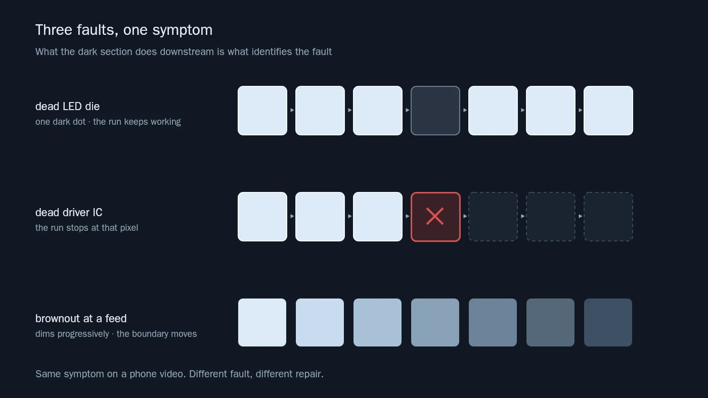
Because "dead pixel led strip" describes three different faults that share one symptom, and they cost wildly different amounts to fix. A pixel can go dark because the LED die inside it failed while the driver IC next to it keeps reshaping data to the rest of the run — the strip continues, one dot is missing. A pixel can go dark because the driver IC itself failed, and on a single-data-line chipset that stops every pixel after it. Or nothing has failed at all: the far end of the run has sagged below the voltage the ICs need, and the boundary between lit and dark moves when the content changes brightness.
The first case is one pixel's worth of strip. The second is the same one-pixel job that most people turn into a fifty-metre replacement. The third is not a pixel problem and no amount of soldering will touch it.
One Dark Pixel, Three Different Faults
The distinction that matters is inside the 5050 package. An addressable pixel is two components sharing a package: an LED die that produces light, and a control IC that receives a serial data stream, keeps its own 24 bits, and re-transmits the remainder to the next pixel. The data path runs through the IC, not through the die. That single fact explains almost everything below.
What you see | What failed | Does the run continue? | First test |
|---|---|---|---|
One pixel dark, everything after it lit and behaving | LED die, or one output channel of the IC | Yes | Single-pixel chase: confirm only that index is dark |
Everything from one pixel onward dark, or frozen on the last colour it showed | Driver IC, or the data joint just before it | No | Bridge past the suspect pixel; if it stays dark, trace the data line back |
Everything from one pixel onward dims with bright content, recovers at low level | Feed or injection, not a pixel | Yes, but unstable | Meter DC at the boundary under full white |
A block of three or six dark LEDs — one pixel, on 12 V or 24 V strip | One IC driving a grouped pixel | No | Same as row two — the whole group is one address |
For a wider comparison of what the different chip families do, the RGB, RGBW and RGBIC pixel strip guide covers the addressing and channel differences; what follows is specifically about what happens when one of them stops answering.
Why the Chain Stops Where It Stops
A WS2812B-class pixel takes the first 24 bits that arrive at its DIN pin, latches them as its own colour — eight bits each for red, green and blue — and reshapes the rest of the stream out of DOUT to the next pixel. The WS2812B datasheet describes exactly this: a data latch, a signal reshaping amplifier, and a cascade output, with a power-on reset circuit and a power-loss reset circuit on board. Every pixel in the run repeats the operation, which is why a strip can be cut to length and why the far end looks identical to the near end.
The order inside those 24 bits is not RGB either. A WS2812B expects green first — the datasheet's instruction is "follow the order of GRB" — so a controller left on the wrong chipset or colour order paints the wrong colours instead of losing a pixel. Check that setting before condemning hardware.
Two numbers from that datasheet do a lot of work here. The device sends at 800 kbit/s, and one bit occupies 1.25 µs. So each pixel costs 24 × 1.25 = 30 µs of the stream. A thousand pixels on one output is 30 ms per frame, which caps that port at about 33 frames a second — the reason large installations end up spread across many ports, but a separate topic. The same datasheet specifies a reset code at the end of a frame: the data line held low for 50 µs or more.
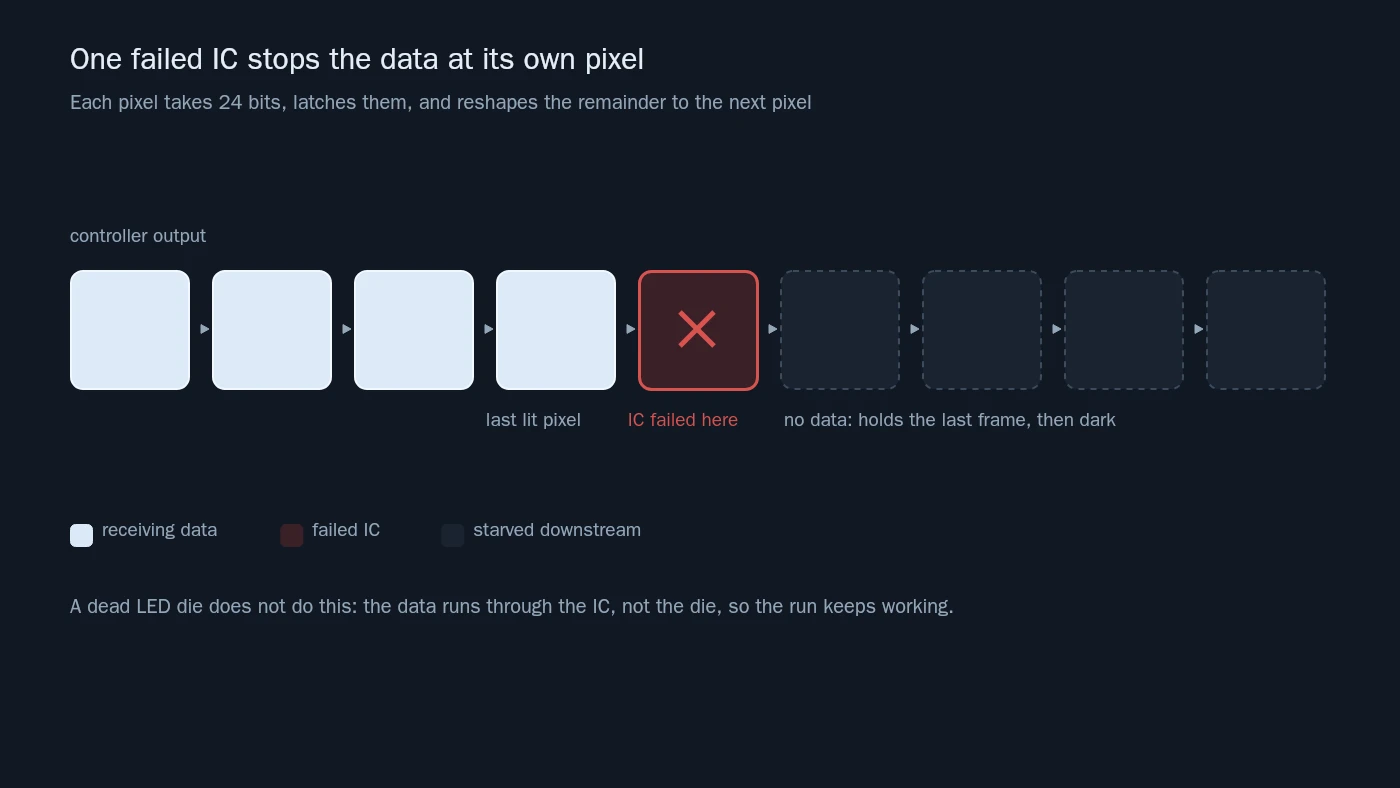
That reset code is why "frozen" is a distinct symptom. When data stops arriving, the pixels that already received a complete frame keep displaying it. They are not broken; they are holding their last latched values and waiting. Chipsets with an internal oscillator keep the PWM running, so a strip whose cable was pulled can sit there showing a perfectly normal still image of the moment the music stopped.
Now the part that surprises people: an addressable pixel does not store an address. There is no ID burned into the IC. Its identity is its position in the stream — it is "pixel 43" because 42 pixels consumed their 24 bits before it. HolidayCoro's mid-span repair procedure states the consequence plainly: pixels get their address from their location in the string, which is why you can splice a strip anywhere and the firmware still sees a continuous run.
Two consequences follow, and both come back when you repair the run:
- An IC that can no longer reshape the stream stops the run at its own position. Everything downstream gets nothing, so it holds the last frame or goes dark depending on what arrived last.
The first of those is what the industry calls a cascade failure: one dead IC takes every pixel after it, and the strip reports it as a section that has gone dark.
- Remove two pixels during a repair and every pixel after them shifts two positions earlier. The strip still lights. The show is now wrong from that point onward, which is a much harder fault to notice than a dark dot.
A failed die does none of this, because the data never touched it. The IC continues to reshape and pass the stream along; its output stage simply drives a dead load. That is why a WS2812B dead pixel in an otherwise healthy run is, in practice, almost always a dead die, and why the chain-break horror stories are always about the IC or the joint feeding it.
One generational caveat: on 12 V strip built around a WS2811 or UCS1903, one IC typically drives three LEDs rather than one, so a single failed IC takes out a group and reads as a three-LED dark block rather than a single dot. If a client hands you an older installation and the "dead pixel" is suspiciously wide, check how many LEDs share an IC before ordering anything. The addressable driver IC guide covers how the IC families differ in addressing and output grouping.
Find the Boundary Before You Cut Anything
The useful output of ten minutes of testing is one number: the index of the last pixel that works. Everything else — which part to order, and whether the next move is a joint, a jumper or a new pixel — follows from that index and from what the downstream side does when you feed it.
Start with the controller's own test mode rather than your show file. Sequences and pixel maps can produce a convincing "dead section" through a patching error, a wrong universe, or a start-index mistake, and the built-in test pattern removes all of that from the question. Only then does the hardware deserve suspicion.
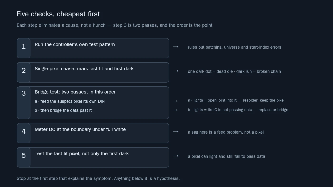
Then walk the strip with a slow single-pixel chase and note the two indices that matter: the last pixel that lights, and the first that does not. That pair is what separates the two faults behind one pixel not working. If the chase runs past the dark spot and lights the pixels beyond it, the run is intact and you have a dead die. If the chase dies at the dark spot and never resumes, you have a broken chain.
The bridge test is the one that pays for itself, and it is really two tests in sequence. With the run powered down, jumper from the DOUT of the last working pixel to the DIN of the first dark pixel, power up, and watch. If the run downstream lights, that pixel is alive and reshaping data — so the fault is the connection into it: a cold joint, a cracked trace, a half-seated pin. Resolder the joint and leave the pixel alone.
If it stays dark that way, move the jumper's downstream end one pixel further — DOUT of the last working pixel to the DIN of the pixel after the dark one — so the data steps around the suspect IC. Lights now means that pixel is dead and the rest of the run is fine. Still dark means the break is further along, and you walk the bridge forward.
Bridge result | What it means | Next move |
|---|---|---|
Downstream lights when you feed the first dark pixel's own DIN | That pixel's IC is alive; the fault is the connection into it | Resolder the joint or re-terminate the connector |
Stays dark that way, lights when you bypass the pixel | That pixel's IC is dead | Replace the pixel, or bridge it permanently and re-map |
Stays dark even bypassed | The break is further along the run | Walk the bridge forward and retest |
Lights, with the colours one pixel out | Expected after a bypass: one data slot is gone | Re-key the map from that pixel onward; the length edit alone does not move the data back |
Flickers or misbehaves | Signal integrity, not a dead pixel | Check ground and data-line length |
Then measure, because a brownout imitates a chain break convincingly. Put a meter across the strip terminals at the boundary while the strip runs full white and compare it with the reading at the feed. A drop of more than a few percent across a short distance is a delivery problem: thin feed cable, a missing injection point, or a supply that is fine at idle and marginal under load. The tell is behaviour, not the number — a voltage sag gets worse with brighter content and moves its boundary when the load changes, while a dead IC is exactly as dead at 5% brightness as at 100%. Diagnosing a dim end of run on site walks the measurement side in detail.
Two field rules worth carrying:
- Suspect the last working pixel as well as the first dark one. A pixel can light and still fail to pass data onward, and cutting only the first dark pixel then leaves you with the same fault one pixel earlier. HolidayCoro's procedure removes both the last working and the first non-working pixel for exactly this reason.
- Look at the joint before the pixel. A cold solder joint, a half-seated connector pin or a cracked pad at a field splice produces a boundary too, and it is cheaper to fix than a pixel. If pressing or wiggling the joint changes the picture, stop testing pixels.
Position one deserves its own rule, because the same dark symptom means something different there. If the first pixel is dark and the second is lit, data reached the run, so that first IC is alive and only its die — or its mapping — is wrong. If the first pixel is dark and everything after it is dark too, the fault is upstream of the strip: the controller output, the DIN joint, or the first IC itself. A first LED that is dead with a dead run behind it is a connection problem before it is a pixel problem.
Mechanical causes cluster at the same place. A strip bent hard against a pixel cracks the trace beside it; a joint that took water in autumn corrodes and starts adding resistance; a splice made with a push-on connector instead of solder fails after a season of thermal cycling. All three produce "dead pixel" complaints and none of them is a dead pixel.
If the symptom is intermittent rather than fixed — a section that drops out in rain, or on bass, or after twenty minutes — the failure is not in this article's territory. Diagnosing flicker on an addressable strip is the better starting point, because a run that comes back on its own is usually a grounding, timing or moisture problem rather than a failed IC.
Dead Pixel LED Strip Repair: Bridge, Cut or Replace
There are three ways to deal with a dead IC, and they are separated by what they do to the addressing rather than by how hard they are to solder.
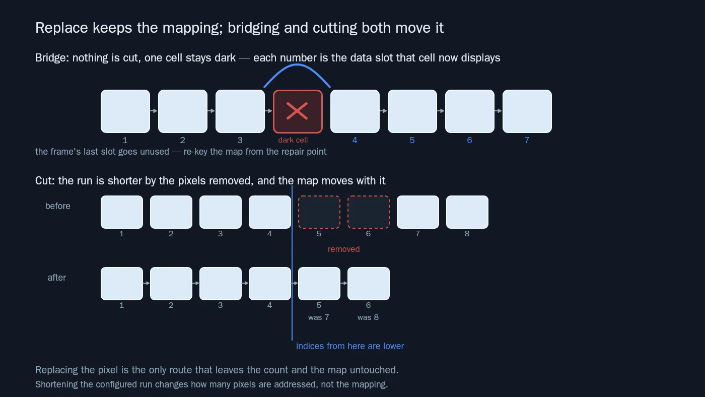
Replace is the only route that keeps both the count and the mapping. Desolder the failed package and fit a new pixel, or replace the metre it sits in, then re-seal the joint. It needs reachable pads and a re-seal, and on a mapped façade — where every pixel is a coordinate in a media file — it is usually the cheapest option over the life of the install, because nothing downstream has to be re-keyed.
Bridge leaves the strip untouched. You run a jumper from the DOUT of the pixel before the failed one to the DIN of the pixel after it, so the data steps around the dead IC. The failed cell stays on the strip and stays dark, and nothing is cut or re-sealed, which makes this the route for anything sealed, awkward to reach, or where the client cannot accept downtime for a soldering job.
What a bridge cannot do is keep the mapping. A bypassed IC consumes no bit slots, so every pixel behind it shifts one address earlier: the cell after the dead one eats the 24 bits that were meant for it, each cell downstream takes its neighbour's slot, and the last slot in the frame goes unused. That shift is arithmetic in the chain, not a controller setting. Shortening the configured length changes how many pixels the controller addresses; it does not push the data back where it was. Only replacing the failed IC keeps the original mapping, so after a bridge you re-key everything downstream of the repair point. One dark cell and a one-position shift, in exchange for no strip surgery.
Cut removes the pixel or pixels and splices the strip back together. The run is shorter by however many you removed, and every pixel after the splice moves that many positions earlier — the same shift as a bridge, only larger and with a clean look instead of a dark cell. Tell the controller the new count and start index so the outputs after this one still start where they should (pixel controllers commonly expose per-output length and start LED, and WLED's LED preferences do this per output), and re-key the map from the splice onward — cutting does not restore the mapping either. What you must not do is cut and say nothing — a 4,000-pixel façade that is two pixels out at the far end will still play, and the fault surfaces weeks later as "the animation is offset on one panel".
Replace the pixel | Bridge (bypass) | Cut and splice | |
|---|---|---|---|
Pixels the controller sends | Unchanged | Unchanged — the last slot goes unused | Set to the new count (the map still moves) |
Downstream mapping | Unchanged | Shifts one position from the repair onward | Shifts by the removed count |
Strip work | Desolder, refit, re-seal | One jumper, nothing cut | Cut, splice, re-seal |
Visual result | Clean | One permanently dark cell | Clean, and the run is shorter |
Best for | Reachable pads, mapped façades, installs that must keep their mapping | Sealed or unreachable installs | Runs where a dark cell is worse than a re-index |
Main risk | Re-seal done badly | Forgetting the one-position shift and the unused last slot | Forgetting that every index after the splice has moved — and that later outputs start earlier |
Whichever route you take, three workmanship rules decide whether the repair lasts a season or a decade:
- Direction is not optional. Arrows on the strip point away from the controller, data enters at DIN and leaves at DOUT. A splice made the wrong way round kills everything downstream of it, and it looks exactly like the fault you were repairing.
- Heat is the enemy, and the neighbouring IC is the victim. Four pads on a 10 mm strip are close together; a soldering iron held on a pad long enough to flow a cold joint will cook the IC beside it. Tin the pads first, use a fine tip, and let the strip cool flat rather than flexing it while warm.
- Re-seal to the rating you started with, not to "waterproof enough". A repair that is electrically perfect and mechanically open fails at the joint within a season, and the second failure reads as a data fault again. Sealing field joints to keep the IP67 rating is the procedure; adhesive-lined heat-shrink plus a neutral-cure sealant is the minimum on anything outdoor.
All of this is low-voltage DC work on the strip side. The supply side of the driver — the mains cable and anything upstream of the DC output — belongs to a licensed electrician: isolate it before you put an iron on the strip, and do not probe a live primary.
Some failures should not be repaired at all:
Condition | Why repair is the wrong call |
|---|---|
Corrosion has spread across several pads | The trace is already compromised; the next failure is weeks away |
Three or more failures scattered along the run | Points to a batch or installation problem, not a pixel |
PCB discoloured or burnt around the pixel | The IC failed short and the copper has been cooked |
Failure sits inside a factory-sealed IP68 extrusion | You cannot restore the seal in the field |
Strip is under warranty or within a project's defects period | A field repair usually voids the claim |
When in doubt, the cheaper test is to replace one section and keep the failed metre. A metre of strip in the van is worth more than an hour of bench time, and it tells you within minutes whether the fault was really local.
When One Pixel Should Not Be Able to Stop the Run
Everything above assumes a chipset where one IC failure breaks the chain. That is a property of the chip, not a law of pixel lighting, and it is the single most useful thing to change at specification time.
Chipsets with a second data line let the next pixel pick up the alternate line when the primary goes quiet. Per WLED's compatibility table, that includes WS2813 at 5 V, WS2815 at 12 V, and WS2805 at 12 V or 24 V; SK6812 is listed as a 5 V or 12 V RGBW option without the backup line, and TM1814 as a 12 V RGBW part. The practical difference is stark: on a run with a backup line, a failed IC leaves one dark pixel and the rest of the installation keeps playing, which converts an emergency into a maintenance item. The trade-offs between the two best-known members of that family are set out in WS2815 versus WS2812B.
What the backup line does not do is worth being honest about. It protects the data path only — a failed feed, a shorted rail or water in a joint still takes the section down. It does not repair anything; you still have a dead pixel to log and eventually replace. And it costs money per metre, which is why a lot of installed strip does not have it. If you are choosing between a backup line and a 12 V architecture for a long outdoor run, the second often prevents more failures than the first, because a higher voltage means lower current, less sag and fewer brownouts that get misdiagnosed as dead pixels.
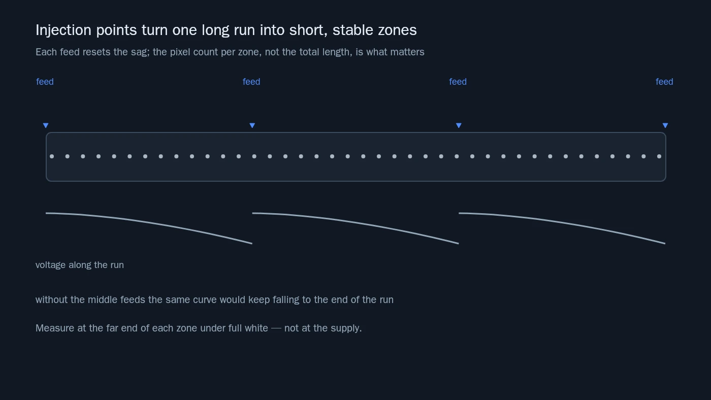
Each feed resets the sag at its own point, so what a zone can carry is set by the number of pixels behind that feed, not by the total length of the run. Split a façade into four fed zones and the dimming question becomes four short runs instead of one long one.
Two smaller choices do a lot for the same reason. Grouped pixels — one IC driving three LEDs at 12 V or six at 24 V — cut the IC count and therefore the failure count, at the cost of coarser resolution and wider dark blocks when something does fail. And the input protection around the first pixel is not decoration: a 300 to 500 Ω resistor in series with DIN, a 500 to 1,000 µF capacitor across the supply at the strip, and a shared ground between controller and supply are the three measures Adafruit's NeoPixel best-practice notes call out, and they prevent the class of failure where a pixel dies on the first power-up rather than in service.
Installation geometry matters more than most spec sheets admit. A strip bent sharply at a pixel concentrates mechanical load exactly where the trace is thinnest; route the bend through the flex gap between pixels, keep a service loop at every joint you might need to reach, and never pull a strip tight around a corner. None of that is electrical, and all of it shows up later as a dead pixel.
What Belongs on the Spec Sheet and in the Spares Box
Almost every failure in this article was decided before the strip was installed — in a purchase order that said "addressable RGB, 60 LED/m, IP67" and left the chip family, the addressing behaviour and the replacement path to whoever was on site. The dead pixel LED strip complaint that starts the service call is, more often than not, a specification complaint in disguise.
Seven lines carry most of the risk:
- IC part number, not "addressable" — WS2812B, WS2815, WS2813, SK6812 and WS2811 behave differently when one pixel dies, and a part number is what lets you re-order the same behaviour five years later.
- Whether the IC has a backup data line, stated explicitly, because it is the difference between one dark pixel and a dark run.
- Pixels per IC group (one LED, three, or six), since that defines what a single failure looks like.
- Voltage class and pixels per port, so the supplier can check the frame budget rather than discovering it at commissioning.
- IP rating per joint, not per strip, plus the sealing method for field splices.
- Spare allowance — a few percent of run length plus a service loop at every accessible joint; on a façade nobody can reach, this is cheaper than any diagnostic procedure in this article.
- A pixel map and a one-page repair procedure at handover, including how to replace a dead pixel without re-keying the run, and what a bridge or a cut costs the downstream addresses. The next technician will not have this conversation.
A supplier who can quote all seven from one factory is also a supplier whose strip, controller and power path were designed against each other, which removes some of these failures before installation. Pileds builds pixel strip and the Art-Net, DMX512 and SPI controllers that drive it in the same plant, with per-batch colour measured on an integrating sphere and a six-step QC process, aging burn-in included, before shipment — which is the answer to "how do I know the replacement metre will match the run I installed three years ago", not to the diagnosis itself. If you are specifying a run and want these seven lines checked against real hardware, send the layout and the pixel count per port to our engineering team through the inquiry form and we will come back with the chip, injection and zoning recommendations for it. If you are starting from the hardware side, the controller range lists the Art-Net, DMX512 and SPI models that pair with it. The zoning arithmetic itself is covered in zoning power for pixel control systems.
The short version, for the next time a run goes dark at pixel 87: find the boundary, bridge past it to find out what is actually broken, then decide whether the fix is a jumper or a new metre. The pixel is almost never the expensive part.
Specifying pixel LED for a real project?
Send the spec — pitch, IC, IP class, run length, voltage — and you get an engineer's answer, not a catalogue. Samples and OEM/ODM quotes from the Shenzhen factory floor.