
Power Zoning for Pixel LED Systems
Zoning decides where a pixel installation fails. How to split a run into protected power zones, size each feed, and document them for the next technician.
Power Zoning for Pixel LED Starts With a Boundary, Not a Distance
A case we see repeatedly: a 36 m facade, eight pixel runs, one 750 W supply, one breaker. At 23:40 on a Saturday the supply fails on a thermal trip and the whole elevation goes dark — not the broken band, the elevation. The fault was one component. The outage was a design decision made months earlier, when somebody ran out of patience and put everything behind one supply.
That decision is power zoning for pixel LED: how many independently supplied, independently protected, independently documented blocks the installation is cut into. It is usually made by default, by following the copper, and it is the single choice that determines what a failure costs, how long a repair takes, and whether the drawings handed to the building mean anything in year four.
A power zone is a group of pixel runs sharing one power supply, one protective device, one isolation point and one boundary on a drawing. Four properties, all of which have to be true at once.
It is not a power injection point, though the two get confused constantly. An injection point is where copper is attached — an electrical detail, one tee, one screw. A zone is an administrative and protective unit: the thing you switch off, the thing you meter, the thing you protect, the thing you hand over. You can add an injection point in an afternoon. Moving a zone boundary means redoing protection, cabling and documentation.
Why it matters beyond tidiness: in most countries the installation rules treat distribution as a set of protected circuits, not one large feed. The IEC 60364 family is the reference most of Europe and much of Asia builds on in name — each country adopts its own edition — and its logic is that a fault is cleared by the device protecting the smallest practical part of the installation — the same logic that gives every socket circuit in a building its own way in the distribution board. A pixel facade wired as one 40 A feed has thrown that logic away, and no amount of good strip gets it back. Your local code governs; the point is that it will be asking you the same question the rest of this article asks.
The Five Limits Every Power Zone Has to Hold
A zone boundary is sound when five limits hold. Not four of them — all five, because each one is the failure mode of the next.
Limit | What it fixes | The number you need | What breaks when it is wrong |
|---|---|---|---|
Current per feed | Conductor size, connector rating | Amps in the zone at full white | Connectors soften, terminals discolour, joints fail in year two |
Voltage drop budget | How far the zone's feed can run | Percent of supply voltage, set at design time | Far end shifts colour before it dims — the customer sees a colour fault |
Supply loading | Supply life and heat | Percent of nameplate at full white | Supply runs hot, derates, or trips on a warm night |
Protection | What clears a fault, and what it takes with it | Fuse or breaker rating, chosen between load and conductor | The device either nuisance-trips or protects the cable instead of the strip |
Isolation and access | Whether anyone can work on it | One switch, one place, reachable | Maintenance requires a second visit, or somebody else's lights go off |
Four of those are arithmetic and the fifth is a site visit — and the fifth is the one that gets skipped: the zone is electrically sound, and then the isolation point ends up behind a sealed panel at 9 m.
A sixth limit belongs to the enclosure rather than the circuit. Whatever IP class the strip carries, the zone's junction boxes and supply housings have to carry at least as much, or the zone has a lower rating than its own contents. Strip rated IP67 glanded into an IP44 box is an IP44 installation, and it will fill with condensation in its first winter.
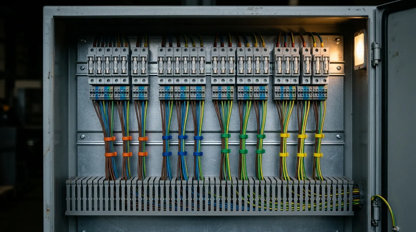
One output per zone, each on its own protective device, is what makes a zone a boundary rather than a branch. Colour coding is the secondary identifier — the primary one is the label, which belongs on the drawing.
Sizing One Zone: From Load Back to a Fuse
The method runs backwards from the strip. Take a real product rather than a rounded example: 18 W per metre at 24 V is the published figure for our PI-10060IC-50S, a DMX512/SPI pixel bar with 60 individually addressable LEDs per metre.
- Metres per run. Say 4.5 m, the length of one elevation band.
- Load. 4.5 × 18 = 81 W.
- Current. 81 ÷ 24 = 3.375 A.
- Runs per zone. Three runs of 4.5 m = 13.5 m = 243 W = 10.1 A.
- Supply. A 350 W unit at 80 % loading carries 280 W — 15.6 m of this bar. The 13.5 m zone draws 243 W, so 37 W (13 % of that ceiling) is spare, and a fourth run does not fit: 324 W is 93 % of nameplate, outside the 80 % rule. Want the reserve? Buy 450 W, where four runs sit at 72 %.
- Protection. 10 A would sit right at the load, so pick the gG rating that leaves a real margin: 16 A from the IEC 60269 gG range (10, 12, 16, 20 A) — 12 A is only 1.9 A above the draw — or 15 A under UL/NEC 240.6. Either sits above the 10.1 A the zone draws and below the ampacity of a 2.5 mm² feed — the gap between load and conductor is the whole job of a protective device.
- Drop budget. Set it now, in the drawing, not at commissioning. Three percent of 24 V is 0.72 V. Everything below has to fit inside that number.
The arithmetic stops at the enclosure door. Mains-side design, protective-device selection, earthing and bonding are qualified-electrician work under the code that applies to the building; this section produces the brief they work from, not an instruction to open a panel.
Step 7 is the one that separates a design from a hope. The physics behind it — resistivity, loop length, why the far end of a run is a different colour rather than simply a dimmer one — is worked through in voltage drop along a pixel run. What matters for zoning is that the budget is a per-zone allowance: if each of eight zones is allowed 3 %, the elevation's worst case is 3 %, and nobody has to guess which band is the bad one. Set a single budget for the whole elevation and the last zone inherits whatever the first one did not use.
Diversity is the number people apply in the wrong place. A pixel show rarely runs at full white across every zone for hours, and the gap is real enough to have a name — diversity factor. It is legitimate when sizing the supply, because heat and supply life are averages. It is not legitimate to use it for the conductor or the protective device, because those are sized for the current that can flow, not the current that usually does. A show that runs one full-white cue per night for ninety seconds still needs a feed that survives that ninety seconds. Apply diversity to the supply, never to the copper.
Once the zone is sized, the supply behind it gets its own method — sizing the supply for a run covers the constant-voltage versus regulated question and the controller's port budget — but the zone is the unit that produces the BOM line.
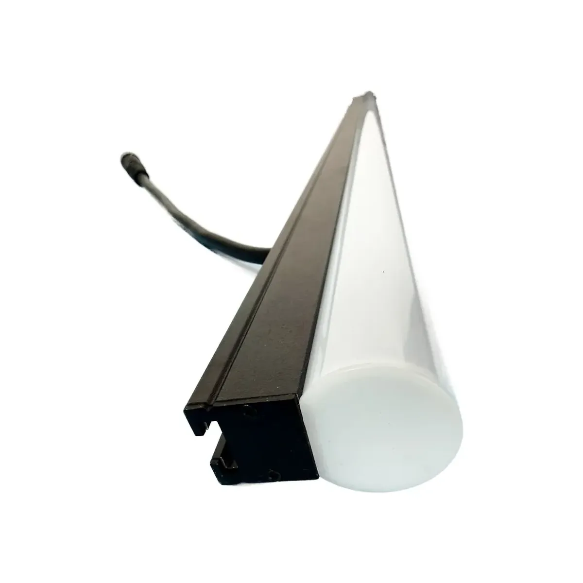
The fixture the arithmetic starts from: our PI-10060IC-50S half-round bar — 60 addressable LEDs per metre, 18 W per metre at 24 V, which is 0.75 A per metre. Every zone limit on this page begins with that one number.
One Supply Per Zone, and What That Costs in Copper
The obvious objection to eight zones is eight supplies: more parts, more terminals, more to fail, and a higher price per watt. It is fair, and it loses to a table.
Feed that 10.1 A zone from a supply 20 m away and see what the cable does at 24 V:
Feed conductor | 5 m | 20 m | 40 m |
|---|---|---|---|
1.5 mm² | 4.8 % | 19.4 % | 38.7 % |
2.5 mm² | 2.9 % | 11.6 % | 23.2 % |
4.0 mm² | 1.8 % | 7.3 % | 14.5 % |
6.0 mm² | 1.2 % | 4.8 % | 9.7 % |
Six square millimetres of copper — a cable most installers would call oversized for a lighting circuit — still loses 9.7 % of the supply voltage over 40 m at this current. The 3 % budget is gone three times over, and the one remaining lever is more copper, which at some point costs more than the second supply it was meant to avoid.
That is the whole argument for one supply per zone: at 24 V you cannot buy your way out of distance with cable, so you move the supply instead. Put the supply near its zone, keep the DC side short, and accept that the AC side is where the long run belongs — the reason a well-built installation distributes mains to local supplies rather than low voltage across a building.
The cost of the pattern is not copper, it is three details that get skipped:
The 0 V reference. Separate supplies do not share a reference automatically. The data line's return has to arrive at the same 0 V the strip uses, or the first pixel sees a signal offset by however much the two supplies differ. Bond the DC negatives at the controller end, not at the far end, and never tie two supplies' positives together: two regulated outputs never sit at exactly the same voltage, so one drives current backwards into the other.
Protective earth and signal reference are different jobs. The mains-side earth on each supply's housing is a protective conductor and has to be continuous and separate, and terminating it is qualified work. The DC 0 V is a signal reference. Running them as one conductor works until someone lifts an earth to chase a hum, and then the data line becomes the earth path.
Inrush adds up. Each supply draws a brief current spike when energised — the inrush current that charges its input capacitors. Eight supplies on one breaker do not add to eight times the running current, they add to eight times something much larger for a few milliseconds, and a breaker chosen on running current will nuisance-trip on a cold morning. Either sequence the zones on, or size the upstream device for the sum of the inrush rather than the sum of the load.
If the copper table says a zone is impossible even with local supplies — a very long band, a high mounting point, no accessible position for a supply — the answer is a higher distribution voltage rather than a thicker cable. The arithmetic for that is in 48 V long-run design.
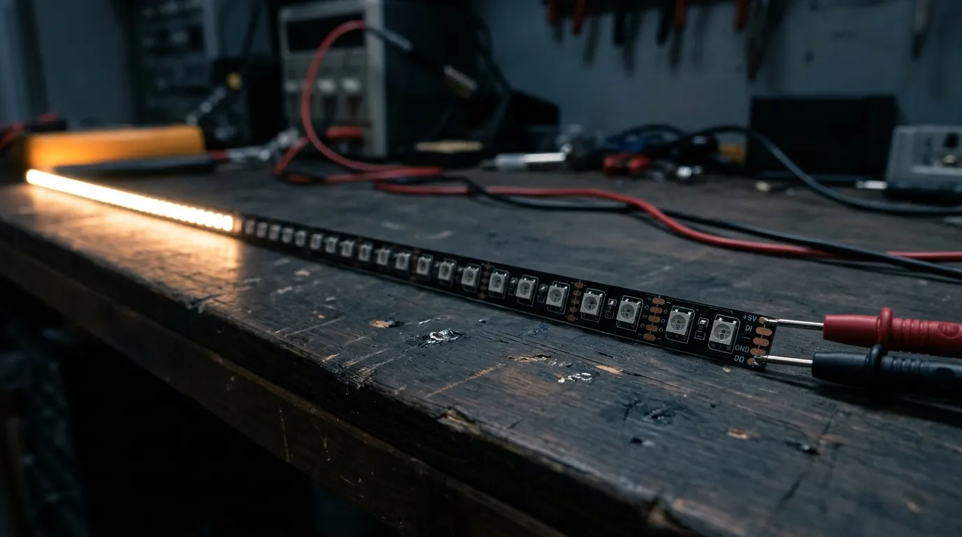
A zone's drop budget is checked at the far end, at full white, with a meter — the same measurement that turns a design number into a commissioning record.
Zoning the Data Path Separately From the Power Path
Power zones are not data zones, and the two counts are rarely equal.
A data zone is one controller output. On an SPI output the pixels are a chain: the controller sends one stream, each driver IC keeps its slice and passes the rest on, so the order is fixed by wiring and the port is the boundary. Break the chain and everything downstream goes dark; that is a property of the protocol, not of the strip.
A power zone can span two ports, and a port can span two power zones — the second happens whenever a long chain is fed at both ends. That crossing is normal and it is also where diagnosis gets expensive: pull one zone's supply and you may take out half of two universes' worth of pixels, which reads on site as "the controller is faulty".
The pixel budget per port is set by the protocol. Over DMX or Art-Net, a DMX512 universe carries 512 channels; a full-colour RGB pixel consumes three of them, so one universe covers 170 pixels. At 60 pixels per metre that is 2.8 m — which means the 4.5 m run from the previous section already crosses a universe boundary and needs two. On a direct SPI port the limit is the port's own pixel capacity instead, and the same 4.5 m run may sit on one port with no universe arithmetic at all. Same pixels, two different schedules — and the schedule has to exist before the cable does.
Practical consequence: keep the zone list and the universe list as two columns of the same drawing, and note which port feeds each zone. When the columns disagree — and they will — the note tells the next technician whether a dark band is a power fault or a mapping fault. That is also the question that decides what parts to send, because the factory builds the controllers and decoders that drive these ports, and port count is a specification decision rather than something to discover on site. The span of options sits with the pixel controllers and decoders, and the protocol question behind them is covered in Art-Net controller options.
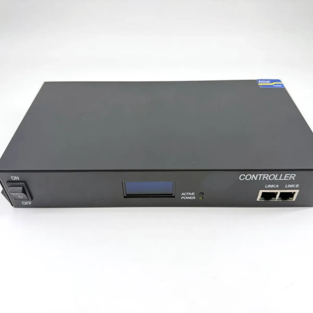
The eight output ports are the data-zone count — decided with the power zones, not after them, because every port boundary is also a place a fault can start.
Five Ways Power Zoning Goes Wrong
Every one of these is common, and every one produces a symptom misdiagnosed as a product fault in the first conversation.
Failure | What it looks like | What it actually is |
|---|---|---|
Too few zones | Far end of a band shifts colour at full white | Current shared through long copper; the drop budget was never written down |
No local protection | One failed run takes a whole elevation | A zone protected by a device sized for the feed, not for the zone |
Zone crosses a service boundary | Repair needs another tenant's lights switched off | Boundary drawn by cable route instead of by ownership and access |
No spare capacity | A fourth run added at commissioning overloads the zone | Zone sized to the drawing, not to the drawing plus a margin |
Zone nobody can identify | Two days of tracing before a repair starts | No label, no schedule, no as-built — the zone exists in someone's memory and nowhere else |
The first has a published procedure — a dim far end has four possible causes and a fixed order to check them in, which is what diagnosing a dim far end on site sets out. The other four are design errors: cheap to fix on paper, expensive on a facade.
A variation of the third catches careful people: the zone is electrically sound but crosses a roof line, a fire compartment or a landlord's metering boundary. The calculation objects to nothing, and then the first repair needs a third party's permission. Draw boundaries along ownership and access lines wherever they disagree with the cable route — the cable can be re-routed, the tenant cannot.
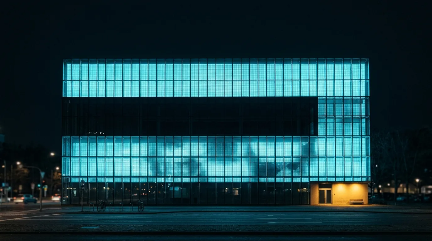
One band out, its neighbours still lit — which is what a zone boundary buys. On a single-supply elevation the same fault takes the whole face, and the report reads "the lighting has failed" rather than "band three has failed". Illustrative image.
What the Next Technician Needs: A Zone Schedule
The zone thesis becomes real when it exists as a document. One table, one page, issued with the installation — the sizing section's three-run zone, three of them on one job:
Zone | Supply / protection | Runs | Load at full white | Pixels / universes | Isolation point |
|---|---|---|---|---|---|
Z01 | PSU-1, 350 W / 16 A gG fuse | R1-R3 | 10.1 A | 810 / U1-U6 | Panel A, isolator 3 |
Z02 | PSU-2, 350 W / 16 A gG fuse | R4-R6 | 10.1 A | 810 / U7-U12 | Panel A, isolator 4 |
Z03 | PSU-3, 350 W / 16 A gG fuse | R7-R9 | 10.1 A | 810 / U13-U18 | Panel B, isolator 1 |
Every column in that table does work that no drawing does. Supply and protection let the next person check the device against the load without metering anything. Universes tell them whether a fault is power or mapping. Isolation point tells them which switch to pull before they touch anything, and which of the two panels it is in. Runs tells them the zone's physical extent without a site walk.
Then three habits that cost an hour and repay it every year:
Label the zone, not the cable. A cable number identifies a reel; a zone number identifies a switchable unit. Print Z01 on the enclosure, on the first and last run of the zone, and in the schedule, and keep colour ties as a secondary cue — colour fades, and the second electrician may not share your palette.
Record the measurement, not the intention. At commissioning, for every zone: supply voltage at the source, voltage at the far end of the last run, current at full white. Those three numbers turn "it looked fine" into a baseline a technician in year four can compare against. If the far end has sagged by 0.4 V since handover, that is a joint, and nobody has to argue about it.
Write down what a zone does when it comes back. Some controllers restore their last state after an interruption, some come up dark and wait for the console. Both are defensible; a building that expects the first and gets the second reports a fault. One line in the schedule settles it, and it is the line that gets left out.
The isolation point does two jobs. For maintenance it is how one zone is worked on while the rest stays live. For egress and emergency it is how the lighting is killed quickly — and that belongs to the installation's emergency arrangements and the building's own systems, not to a controller setting. Give each zone a physical, reachable isolation point, and let the building handle the emergency case. The schedule records which device to isolate; opening it is qualified work.
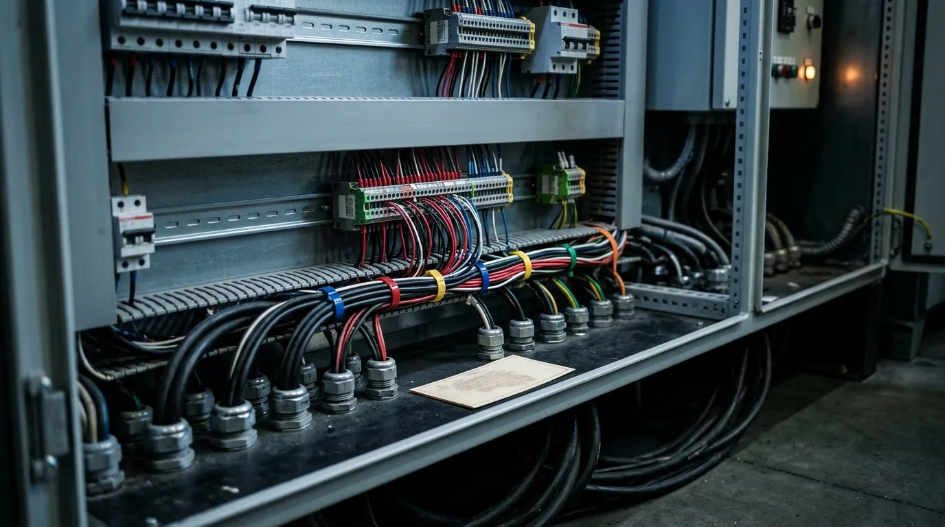
Colour ties group the feeds; the printed schedule is what makes them mean something. Neither survives a handover where the drawing was never issued.
Zoning a 36 m Facade: Eight Zones, One Drawing
Put the method on the 36 m facade from the opening. Same bar, 18 W/m at 24 V, eight bands of 4.5 m. The sizing section grouped three runs per zone; across 36 m that gives 2.7 zones, which is not a boundary anyone can switch off — so here one band is one zone.
- Per zone: 4.5 m × 18 W = 81 W = 3.375 A at 24 V.
- Supply: one 150 W unit per band, loaded to 54 % at full white — deliberately low: a supply at half load runs cooler than one at 80 %, and the bands are in an unventilated riser.
- Protection: a 5 A device per zone, above the 3.375 A load and below the feed's ampacity.
- Feed: 1.5 mm² over no more than 5 m from supply to first run, which loses 1.6 % — inside the 3 % budget with room for the run's own drop.
- Data: 8 zones, 8 chains, 270 pixels per chain — 1.59 DMX universes each at 170 px per universe, so two universes per chain, 16 in total over 2,160 pixels at 60 px/m. One 8-port controller carries all 16 universes with every port used, so what you hold in reserve is a second controller, not a spare port.
- Total: 648 W of load behind 1,200 W of supply, eight isolation points on two panels, and one failure that costs one band instead of the elevation.
Compare that with the opening scene: one 750 W supply, eight runs, one breaker — same load, same strip, and a single thermal trip that takes the whole facade with it on a Saturday night. The eight-zone version costs more in supplies and terminals, and less in everything that happens after handover.
Which is the trade the whole article is about. Power zoning for pixel LED is not a cost you add to a project; it is a decision about who pays, and when — the installer at commissioning, or the building every time something fails. The curtain wall power layout article takes the same method to a full building elevation where the zones follow the mullions and the access strategy follows the facade system.
If you are holding a layout and want the zone split reviewed before the cable is ordered, send the drawing and the five limits — current per band, drop budget, supply loading, protection, access — to our engineers and you will get an answer about your elevation rather than a catalogue. If you have not fixed the hardware yet, the pixel strip accessories guide covers the profiles, connectors and supplies that the zoning method assumes.
Specifying pixel LED for a real project?
Send the spec — pitch, IC, IP class, run length, voltage — and you get an engineer's answer, not a catalogue. Samples and OEM/ODM quotes from the Shenzhen factory floor.