
LED Strip Dim at One End? How to Diagnose It
Bright at the controller, dim at the far end? Probe the run in this order. Four readings, four causes ruled out: wire loss, supply sag, data fault, bad joint.
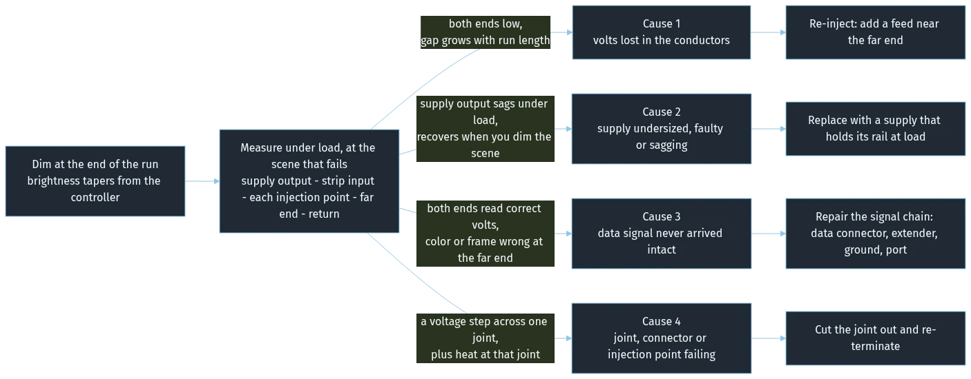
An LED strip dim at one end usually isn't getting enough volts to its last pixels. The description from site is always the same — bright next to the controller, dim at the end of the run — and it is where most installs go wrong: "not enough volts" has four causes on a real job, and only one of them is the wire.
We build addressable pixel strip, and this question arrives from integrators month after month. Nobody needs another explanation of why copper has resistance; what is missing is knowing which two points to put a meter on first.
LED strip dim at one end: four causes, only one of them the wire
A dim far end is a symptom, not a cause. Four faults produce it, each with a different fingerprint on a multimeter.
What is actually wrong | What it looks like on site | Where the meter disagrees |
|---|---|---|
The run or its feeder is losing volts in the conductors | Brightness tapers smoothly from controller to far end, worse on longer runs | Supply output fine under load, far end low — a gap that grows with length |
The supply is undersized, failing, or sagging under load | Whole run a bit dim, supply runs hot, full white drops brightness everywhere | Supply output sags when loaded, and recovers when you dim the scene |
The data or clock signal never arrived intact | Far pixels hold the wrong color, snap to a stale frame, or flicker while voltage reads normal | Both ends read correct volts — the meter finds nothing |
A joint, connector, or injection point has gone high-resistance | One segment after a specific connector is dimmer, or a run that used to be even now tapers | A voltage step across one joint, plus heat at that joint |
Read that top row and stop, and you will spend the afternoon adding feeds to a run whose problem was never the wire — which is why "it's voltage drop" is the least useful answer in pixel installs.
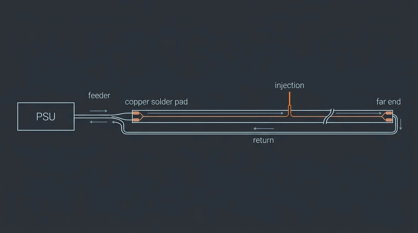
How to test an LED strip with a multimeter before you change anything
Three checks decide whether your readings mean anything.
Rule out the boring cause first. Before you plug a meter in, spend thirty seconds on the things that are not electrical: is the scene brightness in the app turned down, is there a level or power limit programmed into the controller, has the supply got a current limit or dimmed setpoint? A run commissioned at 80% will read perfectly healthy and still look wrong next to the run beside it.
Measure under load, not open circuit. A supply with nothing drawing from it reads its nominal voltage — the number on the label, which tells you nothing. The fault only appears when the pixels pull current: full white at 100%, on the scene that fails. A 12 V supply reading 12.1 V unloaded and 10.4 V under load is not "fine". It is the fault.
Know your meter's tolerance. Portable digital multimeters are typically specified to about ±0.5% on DC ranges — per the standard treatment of multimeter accuracy — which on a 12 V rail is roughly ±60 mV per reading, or about ±0.12 V worst case between two readings. A 0.2 V gap is therefore barely wider than the instrument itself, before probe contact and display resolution are added on top: treat anything under about 0.2 V as noise rather than evidence. Act on the gaps you can see clearly — 0.5 V, 1 V, 2 V.
Then probe in this order, at the brightness level that fails.
Probe point | What you want to see | If it is wrong, this is what you have ruled out |
|---|---|---|
Supply DC output, run loaded | Within about 0.2–0.5 V of the rated rail (12.0 V, 24.0 V) | Nothing yet — this is your baseline. If it sags under load, go to cause 2 |
Strip input pad, at the first pixel | Essentially the same as the supply output | A large gap here is the feeder cable or its terminations — volts lost before the strip starts |
Each injection point, on the strip side of the joint | Matches whichever feed it comes from | A low or dead injection point is cause 4, and it makes everything downstream look like wire loss |
Far-end power pad | Close to the input pad — a healthy run gives up only a fraction of a volt over its length | Nothing — this is the number that matters. Compare the gap against the input pad: a gap you can see clearly (0.5 V or more on a 12 V rail) is the fault you are hunting |
Return conductor, far end and supply | The same reading at both ends | Copper losses happen in both conductors. A lossy return doubles your problem silently |
Adafruit's guidance is that lower voltages are "always acceptable" — with the caveat that the LEDs get dimmer, and that below a limit the LED either fails to light or shows the wrong color. Read that "acceptable" as being about the silicon surviving, not about your installation being fine: a reading that has clearly dropped is already a fault, not merely "slightly dim". The order faults appear in is brightness first, color and dropouts after.
As a working window rather than a datasheet limit: most runs start to look visibly dim once the far end sits more than about 5% below its own input pad — roughly 0.6 V on a 12 V rail, 0.25 V on a 5 V rail — measured against what the input pad actually reads under load, not against the number on the label. How much drop a particular strip tolerates before the color shifts is device-dependent.
Touch the probe tips to copper — the pad, the terminal, the bare conductor — never to insulation or a coated screw head, which invent a fault that is not there.
One safety note: probe a live DC installation deliberately — a slipping probe that bridges two pads on a live rail will arc and weld — and power down to change anything you are touching with tools. If the run is mains-powered rather than 12 V or 24 V DC, stop here: the mains side belongs to a licensed electrician.
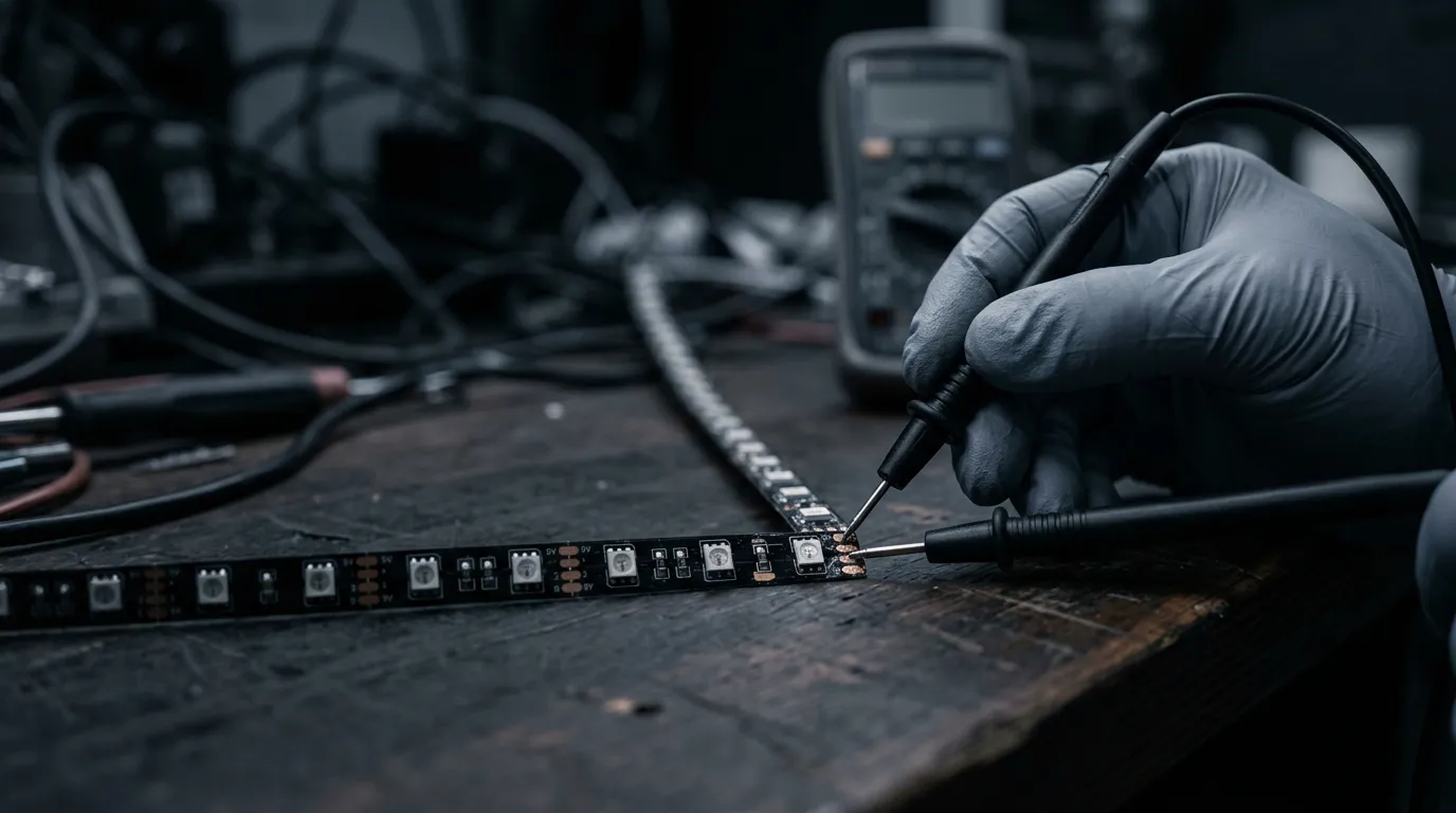
Illustration, not a photograph of a specific installation.
Cause 1 — the far end is getting less than the supply sends
This is the classic reading: supply output correct under load, the input pad agrees, and the far-end pad sits below it by an amount that grows with run length.
The mechanism is ordinary resistance in the conductors. Every meter of copper bus, every meter of feeder cable, and every joint adds a small series resistance, and current through it produces a voltage loss. The symptom scales: longer runs lose more, thin feeder wire makes it worse. Two details shape what you read. The loss happens in both the supply and the return conductor, so a long run can lose roughly twice what a single-conductor estimate suggests — the standard treatment of voltage drop makes the same point about the return path. And a 12 V system shows the fault far more visibly than a 24 V one, because the same volts lost is a much larger share of a 12 V rail.
Where this cause is real, the arithmetic — how much copper, how far, what gauge, how many feeds — is a design question, separate from the job you are doing on site: we have written it up in how to calculate LED voltage drop on long runs. What matters here is the reading, not the formula. And a run that was fine last year and is dim now is not a design problem — check the joints first.
Two things get blamed here and are not this cause: a run uniformly dim from first pixel to last is a supply or brightness issue; and a dead injection point reads exactly like wire loss until you measure the injection point itself.
Cause 2 — the supply is undersized, faulty, or sagging under load
The tell is that the supply's own output moves. Put the probes on the supply terminals, load the run to full white, and watch: a healthy supply holds its rail, a struggling one sags, then recovers when you dim the scene.
Heat is the second tell: a supply near its ceiling in a sealed enclosure drifts as it heats — the classic version is a run that is fine at power-up and visibly dimmer twenty minutes later.
Symptoms of a supply that is too small for the run
If the supply sags, the run is asking for more than it can give. Full white is the worst case for addressable strip: three channels per pixel plus the IC add up fast, and Adafruit's guidance of 60 mA per pixel at maximum white and 20 mA per pixel as a rough rule of thumb — linked under the probe table above — is the standard first estimate. A run that only shows saturated full white in demos, but lives on dimmer scenes in normal use, looks perfectly healthy until someone commissions it at full brightness.
Whether your load means the supply is too small is a sizing question with its own method — see sizing a power supply for pixel LED strip. On site the diagnosis is shorter: the supply sags under load, and the far end's deficit tracks that sag rather than growing smoothly along the strip.
Every reading is a step of elimination. Supply holds its rail under load, far end still low: the wire or a joint is losing those volts. Both ends read the correct rail and the far end still looks wrong: stop measuring voltage — you are looking at the data line.
Cause 3 — the data signal never arrived intact
This is the one nobody writes about, and on addressable runs it wastes the most time: the voltage readings are all correct and the strip still looks wrong.
Addressable strip carries power and data on the same PCB. The data line is a low-voltage serial signal clocked through the pixels in a chain — WS2812B parts, for example, are specified for a supply in the range of +3.5 V to +5.3 V in their datasheet's maximum ratings table, while WS2811 parts run a three-channel constant-current output with a 12 V programmable drive, per the WS2811 datasheet. Data is a different kind of signal from power, and it fails differently.
The fingerprint is color, not brightness. If the first pixels take the commanded color and the far pixels hold a stale frame, drift toward red, or freeze and then catch up, suspect the data path. Long data runs, daisy-chained ports, marginal extender and splitter wiring, and grounding differences between controller and strip all produce this, and it worsens with pixel count: a controller pushing very high node counts shows artifacts at the tail first. The connector side of that chain is where most of these faults sit, which our pixel LED accessories guide covers.
So when your meter says the volts are fine and the far end is still wrong, stop measuring voltage and look at the signal path — including the data connectors, exactly the part most installers assume is fine. If the suspicion falls on the controller's ports and their per-port limits, the Art-Net and DMX controllers are the spec sheets to check against.
Cause 4 — a joint, connector, or injection point is failing
Joints have resistance of their own. Any two conductors in contact — solder, crimp, screw terminal, board-to-board connector, plug and socket — add a contact resistance on top of the copper's. Normally it is tiny: contact resistance typically sits in the microohm to milliohm range, which is why a correct installation disappears into your readings. That same source notes what happens when it degrades — at high current it produces a significant voltage drop and it heats up — and also that contact resistance is not fixed with time, most often falling — a process the same source calls resistance creep. So a joint whose resistance is climbing is already doing something wrong, and it is doing it quietly: take a joint that measured 2 mΩ when you built the run and 200 mΩ two years later; at 5 A that is 1 V lost and 5 W of heat at the joint itself.
That makes the timeline useful: sudden onset points at a supply or signal fault, a run steadily dimmer over months at a joint. Heat, oxidation, a half-fractured solder joint, moisture in an outdoor connection, an un-torqued screw terminal — none announce themselves, they just add ohms.
When a power injection point is not working
A failed injection point does not stop the run: it quietly turns a well-fed installation into a badly-fed one, and everything downstream gets dimmer — which reads exactly like excessive wire loss.
To prove one dead, measure across it, not at it: one probe on the feed conductor where it enters the joint, the other on the strip's pad on the far side, compared with the same measurement at a working injection point. Then measure the feed cable at both ends — a cable with volts at one end and fewer at the other is losing them in the cable or its termination. Finally check for heat at the joint under load: a warm connector at a low-current point is a resistance found. And if the injection point is the fault, the next question is how many feeds the run should have had in the first place: placing injection points inside their current limit works that out feed by feed.
The order to check them in
Onset timing halves the list before you open a toolbox.
How it started | First checks, in order |
|---|---|
Bright, then suddenly dim — after a move, a storm, a re-wire, a power event | Supply output under load (cause 2), then the data path (cause 3). Sudden faults are electrical, not gradual wear |
Steadily dimmer over weeks or months | Joints, connectors and injection points (cause 4). A degrading joint's resistance climbs; copper does not |
Dim from day one of a new installation, tapering toward the far end | Conductors and feed (cause 1), then whether the supply has capacity for the actual load (cause 2) |
Fine at low brightness, dim or flickering at high brightness | Supply capacity (cause 2), then the return conductor (cause 1). This is a load-dependent sag |
If the run has not been powered yet, it is cheaper to work through the commissioning gates before first power than to diagnose a faded far end afterwards.
What to do when you find it
Each cause has one honest fix, and none of them is "buy a new strip".
- Volts lost in the conductors: re-inject. Add a feed at or near the far end rather than replacing the strip. Injection wire sizing is not a matter of taste — a feed run that drops more than about 10% of the rail has moved the problem rather than solved it, which is the working rule in QuinLED's power injection guide. Its worked examples treat a single feed at one end as roughly 4 A of capacity and a feed into the middle as roughly 8 A.
- A sagging supply: replace it with one that holds its rail at your measured load. Fixing the wire will not fix a supply that cannot hold 12.0 V.
- A broken data path: repair the signal chain — the data connector, the extender, the shared ground, or the port. Voltage work will never fix this one.
- A failing joint: cut it out and re-terminate. Do not re-flow solder over an oxidized joint and call it repaired.
For a run where the far end is a permanent design constraint, one manufacturing answer is to stop fighting the loss: a DC48V long-run pixel strip delivers the same power at about a quarter of the current, which cuts the volts lost in the conductors to roughly a quarter — and that smaller loss is then measured against a rail four times higher.
On our own line, the equivalent of this check happens six times before a strip ships: incoming QC, in-line automated optical inspection, a per-batch integrating-sphere color and lumen test, a constant-temperature and humidity aging test, an IP test, and a pre-ship function test. The reading you take on site is the same question at the other end of the journey.
One closing habit saves the next person a day: record what you measured — the readings, the scene brightness, the date, a photo of each joint — and keep it with the installation. When a supplier asks whether a strip is faulty or a run is underfed, that record is the whole argument. And when the far-end reading is low but the visible symptom is only mild, do not file it as fine: record it as your baseline and re-measure in a month, because a contact gap does not close itself.
If the far end turns out to be a design constraint rather than a fault, send us the readings and we will tell you whether the strip specification or the feed layout is the mismatch.
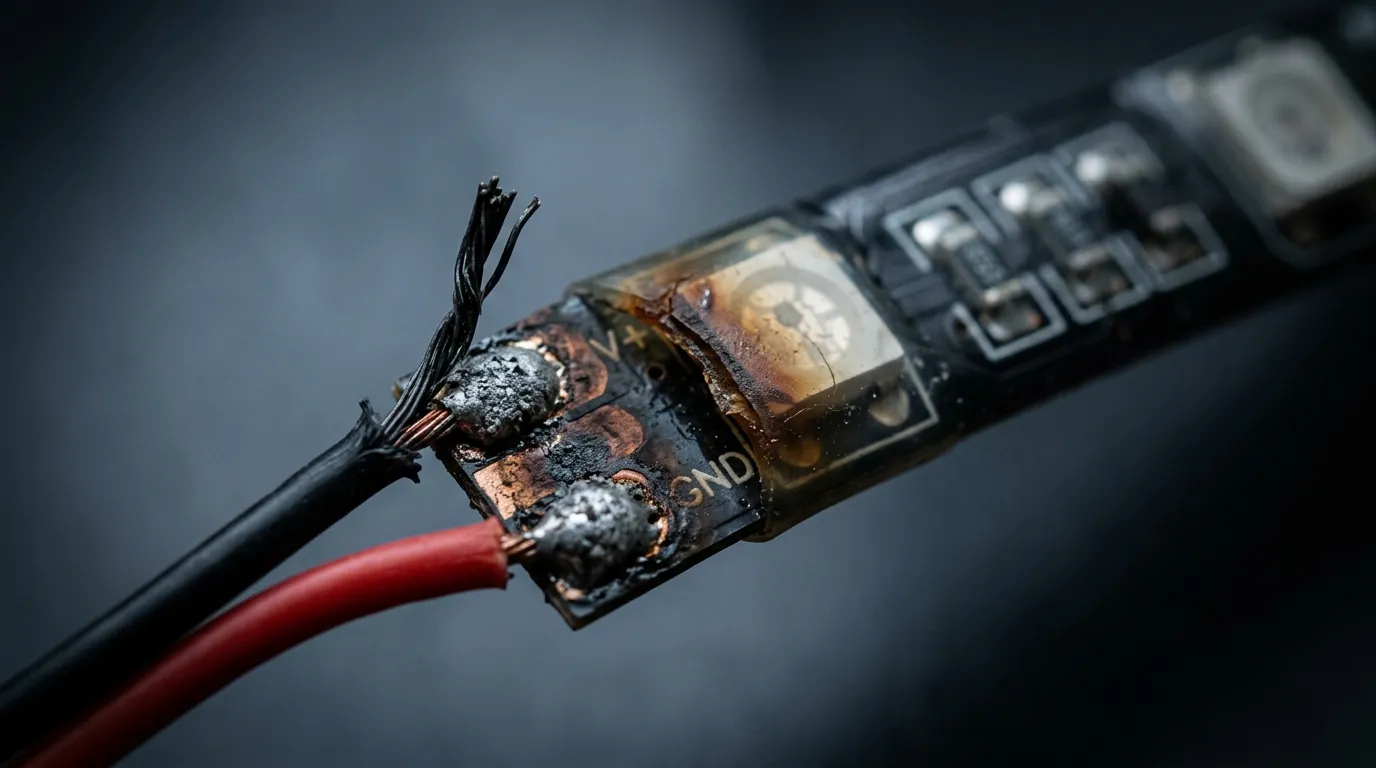
Illustration, not a photograph of a specific installation.
FAQ
Why is the far end dim and not the whole run? Because the loss accumulates with distance: every meter of conductor adds resistance, so the far pixels see the rail minus everything the run has lost. A run that is evenly dim, first pixel to last, points at the supply or the brightness setting instead.
Why are half my LED strip lights dim? When a run is dim in one half rather than tapering, look for a boundary: a connector, a cut-and-rejoined section, or a failed injection point. A taper is gradual; a step is a joint.
My strip is dim and flickering. Which cause is that? Flicker usually means the supply or the signal, not the wire. A supply near its limit can drop out momentarily; a data path with a bad ground can flicker in step with the scene. A pure conductor loss dims smoothly.
Does 5 V, 12 V or 24 V change what I'll measure? It changes how bad it looks, not how you diagnose it: the same volts lost is a much greater proportion of a 5 V rail than a 24 V one. Which rail to choose for a new build is covered in 12V vs 24V vs 48V for pixel LED strip.
Specifying pixel LED for a real project?
Send the spec — pitch, IC, IP class, run length, voltage — and you get an engineer's answer, not a catalogue. Samples and OEM/ODM quotes from the Shenzhen factory floor.