
LED Strip Light Flickering: Pixel-System Fixes
Most flickering-strip advice stops at the power supply. On addressable pixel systems, read the pattern first: power, data or refresh rate decides the fix.
If you searched for led strip light flickering, you probably have a strip on a bench or a wall right now, and it is doing something it did not do yesterday. The advice you are about to find elsewhere — bigger power supply, reseat the connectors, check the dimmer — is written for constant-voltage tape, the kind where every LED on the reel does the same thing at the same time.
An addressable strip is not that. Each LED on it has a driver chip with its own address, its own latch, and its own slice of a serial data stream. When a pixel strip flickers, the strip is usually doing exactly what it was told. The fault is somewhere upstream of the light: in the current that feeds it, in the signal that addresses it, or in the clock that keeps rewriting both.
That distinction changes what "why is my led strip light flickering" actually means on site. On a single-colour tape, flicker is almost always one fault. On a pixel system it is a symptom that maps to three separate layers, and the layers have completely different fixes. Replace the power supply on a data fault and you will have spent money to watch the same flicker.
Why the Usual Flicker Checklist Misses Addressable Strip
Consumer guides treat flicker as a power-delivery problem because on 12 V tape it almost always is. The load is simple: a resistor and three LEDs per segment, no logic, no addressing. Undersize the supply and the whole run pulses together. Loosen a clip and the section after it goes dark.
Add a driver IC per pixel and the failure modes multiply, but the visible symptoms move in a specific direction. Power problems stay global — the whole run, or everything past a feed point. Data problems become local and digital: wrong colours, pixels out of sequence, a segment that jumps to a random hue, a strip that runs a test pattern perfectly and then corrupts the moment real content arrives. Time problems look like stutter: the whole installation updates at eight frames a second instead of forty, or it looks clean to the eye and bands on camera.
For a refresher on what separates these strips at the component level, the RGB, RGBW and RGBIC pixel strip comparison covers which chip families do what. What matters here is simpler: a pixel strip carries two supplies — power and data — and they fail in different ways. Most on-site misdiagnosis comes from fixing the wrong one.
Layer | What it has to deliver | What breaks it | How the flicker presents |
|---|---|---|---|
Power | Current at a stable voltage | Undersized supply, thin feed cable, no injection point | Whole run together, or everything downstream of one feed |
Data | Addresses and colour values | Missing ground, over-long cable, logic-level mismatch | Random pixels, wrong colours, a block that jumps after a joint |
Time | Frames per second | Too many pixels on one output, protocol ceiling | Stutter that starts at a pixel count, banding on camera |
Read the Pattern First: A Field Matrix
Before touching a screwdriver, describe the flicker out loud. Rhythm, scope, and trigger are enough to eliminate two of the three layers most of the time.
Rhythm means how it pulses: steady, random, or content-dependent. Scope means what moves together: the whole run, one segment, one pixel, or every Nth pixel. Trigger means what makes it start: power-on, a white frame, a bass drop, a camera, rain.
A phone is a better instrument than your eyes for two of these. Record two seconds at 240 fps and step through the frames. Human vision integrates pulses above roughly 60 Hz into steady light, so a strip that looks fine can be dropping every other frame, and a strip that looks like it is strobing may be running at a perfectly normal refresh that beats against the camera's shutter.
What you see | Layer | Most likely cause | 60-second test |
|---|---|---|---|
Whole run pulses about once a second, then recovers | Power | Supply in hiccup or thermal shutdown | Measure DC at the supply output while it pulses |
Clean at low brightness, flickers on white or full output | Power | Brownout on current surge | Play full white, measure at the far end of the run |
Random pixels show wrong colours, worse past a certain point | Data | Missing ground reference or over-long data line | Jumper supply negative to controller ground |
One segment dead or strobing, upstream perfectly fine | Data | Damaged pixel input or wet joint | Swap in a known-good segment |
Flicker starts at a pixel count, not at a distance | Time | Refresh budget exceeded on that port | Halve the pixel count on the port |
Bands roll across the strip on camera only | Time | PWM frequency against shutter | Re-record at 240 fps and compare |
Colours step and collapse at low brightness | Time | 8-bit PWM running out of duty-cycle resolution | Test at 50% brightness |
Every joint flickers after transport, worse in rain | Data | Moisture ingress in the joint | Inspect and re-seal one joint |
Two rows deserve emphasis because they break the usual intuition. A brownout on a full-white frame looks exactly like a data corruption — the strip goes to random colours because the driver chips lost their latched values and are re-reading garbage on power-up. And a refresh-rate shortfall does not look like a fault at all under stage light; it looks like a slightly cheap installation.
Layer One — Power: The Brownout That Looks Like a Data Fault
A pixel strip's current draw is not constant. It scales with what you ask the strip to display. A WS2812B-class pixel at full white pulls roughly three times the current of the same pixel at a saturated primary, and a full-white frame across a long run is the worst case the supply will ever see.
That surge matters because of what happens at the bottom of the dip. Each driver chip needs a supply inside its rated window — 5 V nominal, with 3.5 to 5.3 V as the absolute maximum for a WS2812B in the WS2812B datasheet — and it has a power-on reset circuit that clears its latch when the rail collapses. Drop below the threshold for a few milliseconds and the chips behind that point reset. They come back with no colour data latched, and until the next frame arrives they show whatever their inputs are picking up. On a long run, that reads as a band of pixels flashing random colours at the far end whenever the content goes bright.
Which is why "the strip has a data problem" and "the supply is marginal" produce the same phone video. The test that separates them is measurement, not opinion. Put a meter on the strip terminals at the far end, play a full-white frame, and read the DC value under load. A supply that reads 12.0 V at its own terminals under load and 10.6 V at the far end of a 12 V run is telling you the problem is delivery, not logic.
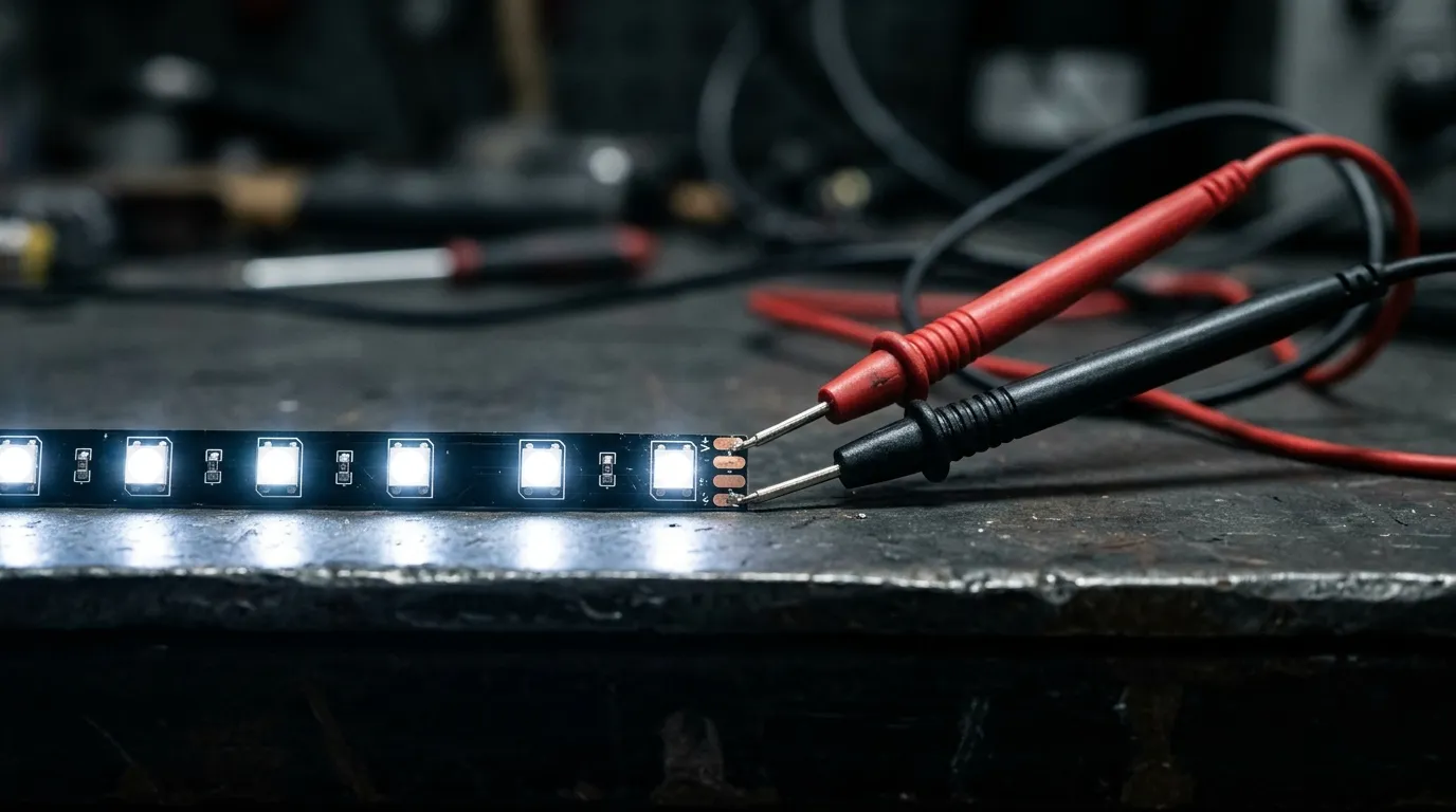
Three numbers decide most of these cases:
- Total load versus supply rating. Add up watts per metre across every run on the supply, then keep the continuous load to about 80% of the rating. The remaining headroom covers inrush, ambient derating, and the fact that a supply rated at 30 °C inside a sealed enclosure is not rated at 30 °C.
- Feed cable, not strip length. Voltage drop is a function of current and conductor cross-section. Thin feed cable between supply and strip end causes the same sag as a long strip. The mechanics are covered in more detail in voltage drop on long LED runs.
- Injection points. Past a certain length, the fix is a second feed rather than a bigger supply. Feed the middle, feed both ends, and keep the data line continuous in one direction. Zoning power for pixel control systems covers how to split a run so that each zone has its own feed without breaking the data chain.
Two clean-ups in this layer are cheap and often enough. First, check whether the supply is doing anything else — a controller, a router, a fan on the same rail all eat the headroom you thought you had. Second, check the dimming path. A mains-side dimmer feeding a switching supply is a known flicker source, and mixing a phase-cut dimmer with a supply that was never designed for one produces exactly the rhythmic pulsing people describe as a bad driver. If the flicker only appears when the dimmer is in circuit, the dimmer is the fault, not the strip.
Anything on the mains side is a job for a licensed electrician. Low-voltage DC checks with a meter are the boundary of what belongs in a site checklist.
Layer Two — Data: Ground, Length and the 5 V Logic Gap
The single most common cause of bizarre flicker on an installed pixel system is a missing common ground. A controller powered from one source and a strip powered from another have two different references for "zero volts". The data line's high and low thresholds are measured against the controller's ground, while the pixel's input comparator measures against its own. The result is a data stream that is perfectly valid at one end and marginal at the other, so pixels interpret bits inconsistently. The symptom is unmistakable once you have seen it: correct colours for a while, then a pixel or a block jumps to a random colour, then it recovers.
One conductor between the supply negative and the controller ground fixes it. That is the whole repair. It is also the cheapest test in this article, which is why it belongs near the top of any field procedure.
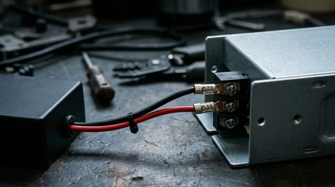
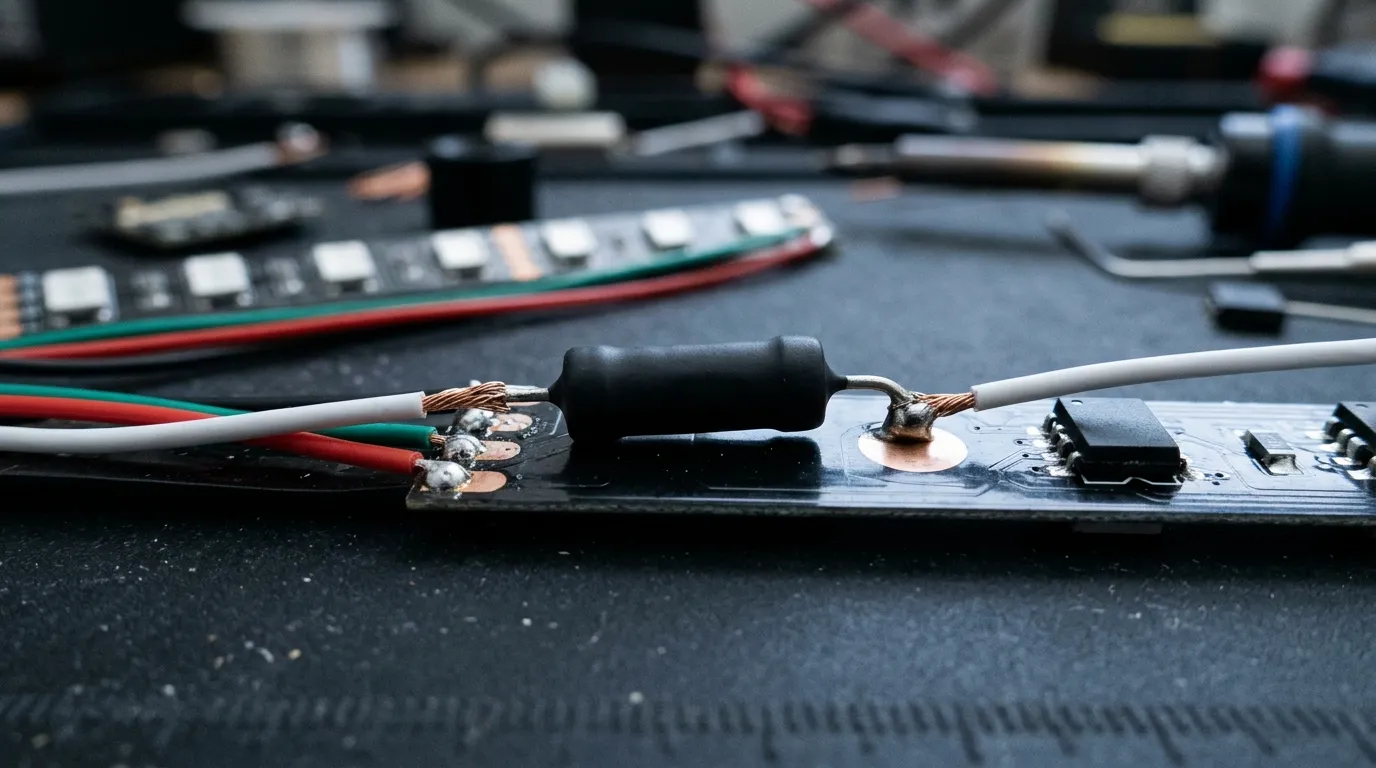
The second cause is signal integrity over distance. The data line between controller and first pixel is a single-ended logic signal, not a differential bus. It has no error correction and no retry — a corrupted bit is simply a wrong colour. Adafruit's NeoPixel best-practices notes recommend a 300 to 500 Ω resistor in series with the data line at the first pixel, which limits ringing and protects the first chip's input from reflected energy. Put it at the strip end of the wire, not the controller end.
The third is a voltage mismatch that bites when someone drives a 5 V strip from a 3.3 V microcontroller. A WS2812B wants a data high above roughly 0.7 × VDD, so at 5 V supply that is about 3.5 V — above what a bare 3.3 V pin delivers reliably. Sometimes it works on the bench and fails after the cable gets longer, which is the worst kind of intermittent. The fix is a level shifter at the controller, and WLED's wiring guidance covers the standard arrangement, including why a level shifter plus a resistor plus a shared ground is the baseline rather than an upgrade.
Length is where installers get caught. A few metres of unshielded data wire is fine. Forty metres of it, run beside mains cable, is an antenna. Past roughly 10 to 15 m, either move the controller closer, use a differential driver/receiver pair, or accept that the fault will move with the cable and stop blaming the strip. Long data runs and the DMX/Art-Net alternative are covered in the Art-Net controller overview.
Two mechanical faults also live in this layer:
- Reversed direction. Data goes in at DIN and out at DOUT. A joint made the wrong way round kills everything downstream of it, and a joint made intermittently produces flicker that starts exactly at that joint.
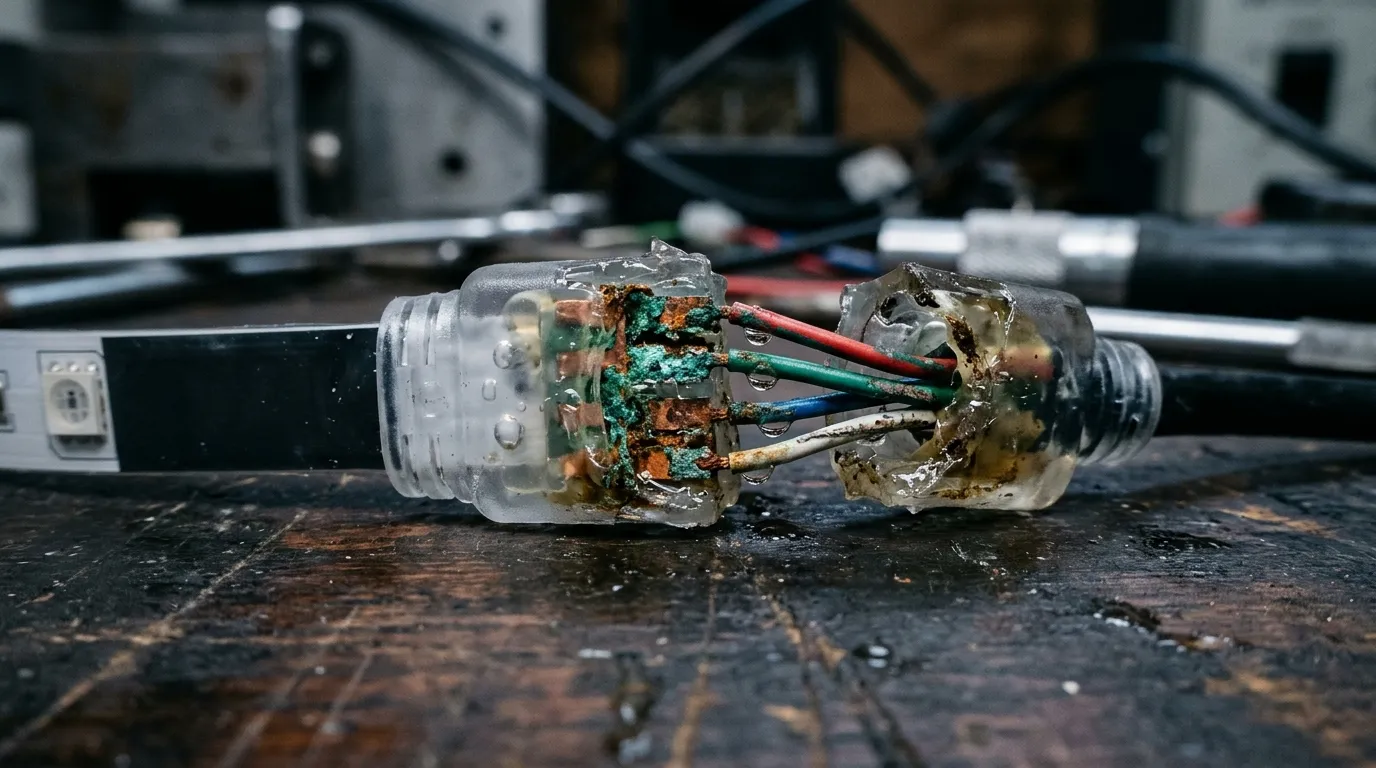
- Moisture. A gel-filled IP67 joint that was not fully seated passes a little current, corrodes, and starts to add resistance. The flicker appears in rain and disappears when it dries out, which is a diagnostic in itself.
One design note worth knowing before you order: not all chips fail the same way. A WS2815 carries a backup data line, so a single dead pixel does not take the rest of the run with it — useful on facades and anything you cannot easily reach. A WS2812B does not, so one damaged chip blacks out everything after it. The trade-offs between the two are set out in WS2815 versus WS2812B.
Layer Three — Time: Refresh Rate Is a Budget
Every pixel on a strip has to receive its own data before the frame can be displayed, and the stream is serial. On a WS2812B at 800 kbit/s, each pixel consumes 24 bits, so the controller spends about 30 µs per pixel, per frame. That number is not a specification you can negotiate — it is arithmetic, and it sets the ceiling on how many pixels one output can refresh.
Pixels on one output | Time to send one frame | Maximum refresh |
|---|---|---|
256 | 7.7 ms | 130 fps |
512 | 15.4 ms | 65 fps |
1,024 | 30.7 ms | 32.5 fps |
2,048 | 61.4 ms | 16.3 fps |
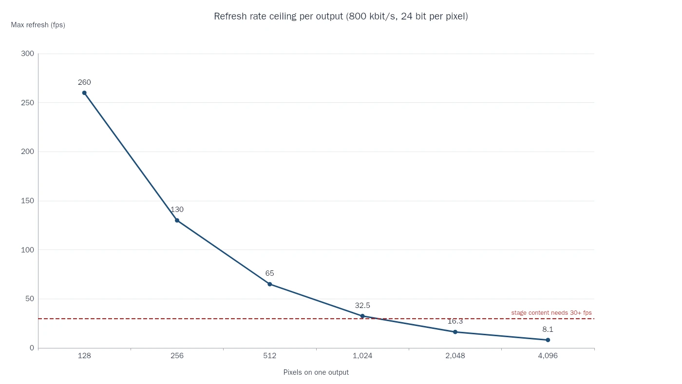
Two things follow. First, a strip that flickers only above a certain pixel count is not faulty; it is being asked for more frames than the data rate allows, and the controller is skipping or truncating. Splitting one port into two is the fix, and it costs a controller port rather than a new strip. Second, high pixel counts are why 16-port and modular controllers exist at all: the constraint is per output, not per installation.
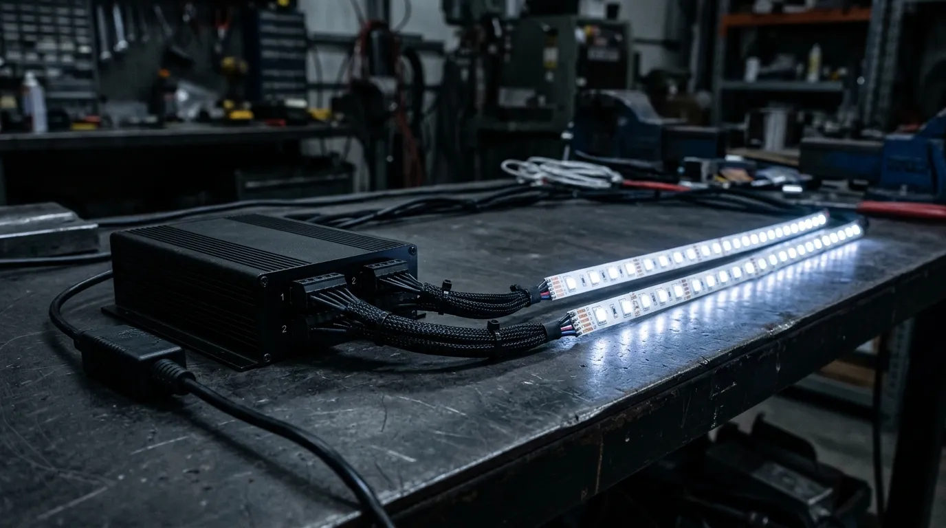
Above the pixel layer sits the protocol. DMX512 gives you 512 slots per universe, and at three slots per RGB pixel that is 170 pixels per universe — a number worth memorising, because it explains why large pixel walls need many universes. ANSI E1.11, the DMX512 standard, also sets the channel timing, and with all 512 slots in use a full frame tops out around 44 Hz. Art-Net carries those same universes over Ethernet rather than a serial line, and per the Art-Net specification that 44 Hz is the ceiling for a node that outputs DMX512.
It is not the ceiling for your pixel strip. An Art-Net-to-SPI node can declare a higher refresh rate, and it should, because the per-port pixel budget above is the tighter constraint anyway: 170 pixels take about 5 ms to send at 800 kbit/s, which is roughly 200 fps if the node lets you ask for it. The 44 Hz figure is a DMX512 limit, not a physical one — worth knowing, because it decides whether adding universes will help you or whether you are already past the point where it matters.
A 44 Hz DMX ceiling is fine for almost all architectural and stage work, and it is the wrong tool for video. Playback at 60 fps through DMX512 output gateways means the last 16 frames never leave the controller, and the fix is more universes or an SPI path, not a better cable.
One more time-domain effect is worth naming because it is misdiagnosed constantly: brightness. Colour is driven by pulse width, and an 8-bit channel gives 256 steps. At 1% brightness the driver is switching on for a very short window, and the effective resolution at the bottom of the scale is only a handful of steps — which is why some pixel strips shimmer or step visibly when dimmed to near-black on camera. Raising the master level and lowering the camera exposure fixes the shot; nothing is broken. For the mechanism behind that, how SPI and PWM divide the work is the short version.
The Five-Step Field Procedure
Ordered by cost, not by likelihood. Each step eliminates something, and every step happens before anyone climbs a ladder to replace hardware.
- Record the pattern. Two seconds at 240 fps on a phone. Name the rhythm, the scope and the trigger. This step is free and it decides which layer you are working in.
- Bond the ground. One jumper from supply negative to controller ground, then replay the same content. If the flicker stops, you are done — and you have learned something about the rest of the installation.
- Meter the DC under load. Read at the supply terminals and at the far end of the run with full white on screen. More than about 5% sag between the two points means the delivery path is the problem, not the strip.
- Split the port. Halve the pixel count on the output that flickers, or move half the run to a second output. If the flicker disappears, you were over the refresh budget, and the permanent fix is more ports or a shorter run per port.
- Substitute a segment. If the flicker is localised, swap in a known-good metre or fixture. A fault that travels with the segment is the segment; one that stays put is the wiring or the controller.
If the flicker survives all five, the remaining candidates are a failing pixel driver at a specific address, damaged cable insulation, or a controller output stage. At that point the measurement you want is a scope on the data line at the first pixel — square edges with clean rise times, or rounded ones that explain everything. The same end-of-run logic applies to dimming faults and is set out in diagnosing a dim end of run on site.
A note on sequencing: the temptation is to start with the power supply because it is a single part and swapping it feels decisive. On pixel systems that is the most expensive first move and the one least likely to be right. Ground bond, meter reading, and port split cost nothing and cover most of the real cases.
What to Write on the Purchase Order
Every failure in this article was decided before the strip was installed — in a specification that named a colour, a voltage and a length, and left the rest to the integrator. The purchasing document is where flicker gets designed out.
Seven lines carry almost all of the risk:
- Driver IC, by part number, not by "addressable". WS2812B, WS2815, SK6812, UCS1903 and SM16703 have different failure behaviour, reset thresholds and backup-line behaviour.
- Voltage and pixels per metre, together. A 5 V strip at 60 px/m and a 24 V strip at 60 px/m are different products with different feed requirements.
- Pixels per output at the controller, so the supplier can check it against the data rate rather than leaving it to commissioning.
- Data interface — SPI, DMX512, or Art-Net — and whether the controller is supplied with the strip.
- Power injection points, or a stated maximum run length per feed.
- IP rating per joint, not just per strip, plus the sealing method for field joints.
- Colour consistency tolerance across the batch, since a strip that shifts hue along its length reads as a fault even when the electronics are perfect.
Most of these are cheap to specify and expensive to discover. A supplier who can quote all seven from a single factory is also a supplier whose controller, strip and power path were designed together — which removes the ground-reference and level-mismatch failures in Layer Two before they exist. That is the reason the controller and the strip should be specified as one system, whether the controllers are ours or anyone else's.
Pileds builds both ends of that system: Art-Net, DMX512 and SPI controllers matched to pixel strip and bars built in the same factory, with per-batch colour measured on an integrating sphere rather than eyeballed, and a six-step QC and aging process before shipment. If you are specifying a run and want the seven lines above checked against real hardware, send the specification to our engineering team and we will come back with the pixels-per-port, injection and IP recommendations for your layout.
Specifying pixel LED for a real project?
Send the spec — pitch, IC, IP class, run length, voltage — and you get an engineer's answer, not a catalogue. Samples and OEM/ODM quotes from the Shenzhen factory floor.