
Mounting LED Strip in Uneven Tunnel Sections
Tunnel LED strip mounting on a wall that is never flat: set the light line first, pick the fixing, allow for expansion, cut for the curve and seal every fixing.
Every specification for tunnel lighting assumes a surface. The surface is the one thing nobody supplies. A tunnel section is drilled, blasted, scaled, sprayed and bolted, and the result is a profile that wanders: overbreak behind the design line, shotcrete of uneven thickness, an arch that changes radius at the haunch, mesh and bolts standing proud of the rock, and transitions where a drift widens or a curve starts.
Tunnel LED strip mounting is therefore not a choice of clip. It is a sequence of four decisions that have to be made in order: where the light line runs, what holds the strip to an uneven surface, how much movement the run has to absorb, and where it may be cut. Get the order wrong and the run looks fine at commissioning and fails at the first re-tensioning, or the crew cuts a flexible strip where the factory never intended a cut.
This article works through that sequence with the numbers that actually decide it, and ends with a mounting schedule you can hand to the crew and a short list of what a supplier needs in order to quote the fixing package.
Why a tunnel section is never the surface on the drawing
The design line on a tunnel drawing is a boundary, not a wall. In drill-and-blast excavation the profile routinely sits behind that boundary — overbreak — and the void is then filled with sprayed concrete, so the finished surface is a rough, undulating skin whose thickness varies along the run. Sprayed concrete linings are applied over mesh and bolts, which means the surface the installer actually sees is a composite of rock, wire, plate and concrete, not a plane.
Four things follow, and each one breaks a different assumption:
- Overbreak means a straight mounting line drawn between two surveyed points will stand off the wall in some places and foul it in others. The strip has to be fixed to a path, not a line.
- Roughness means adhesive is not a fixing method underground. Dust, damp and a surface profile measured in centimetres defeat tape, and a strip that comes down over a roadway is a hazard, not a defect.
- Support hardware — mesh, rock bolts, steel arches, timber props — is often the only structure that is actually stable enough to hang from, and it is neither flat nor evenly spaced.
- Section changes — widening at an intersection, a curve, a portal transition, a rise in the back — are where the geometry and the electrical design stop agreeing with each other.
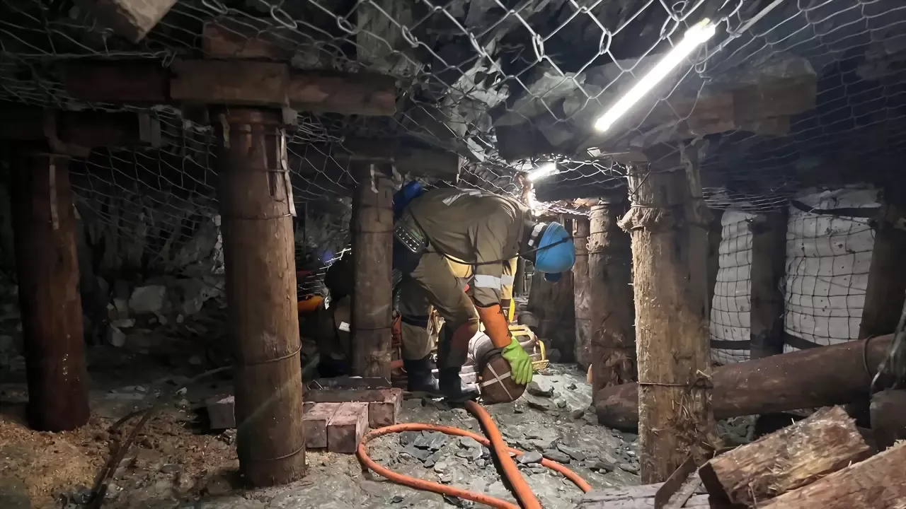
Above: the surface a mounting drawing assumes versus the one crews meet — mesh, timber props and an uneven back. The strip is tied to the support, not to the rock, in the 10,000 m AC36V run delivered to a South African mine.
If that is the surface, then the environment acting on it is the second constraint. Water, dust, vibration from drilling and haulage, and impact from machinery are covered in what underground lighting has to survive; mounting is where those three demands become hardware, or where they are quietly ignored.
Everything below assumes the supply and the model family are already settled — the AC36V mining and tunnel lighting buyer's guide is where that, rather than the installation, is decided.
Three ways to fix a run — and where each one fails
There are only three families of fixing in a tunnel, and the choice between them is decided by the substrate, not by preference.
Method | What it fixes to | Works when | Fails when |
|---|---|---|---|
Strapped to structure — cable ties, stainless straps, wire | Mesh, rock bolts, arches, timber props, conveyor frames | The support is continuous and load-bearing; the run must follow a curved back or an irregular wall; installation has to be fast and re-doable | Ties are over-tightened on a soft jacket, or spaced so far apart that the run sags into the clearance envelope; UV and abrasion chafe the sheath where it crosses wire |
Suspended on a catenary or messenger wire | A tensioned wire strung between anchors | The roof is high, unstable or inaccessible; the run has to be relocated as the face advances; a long straight span with few fixing points is wanted | Anchors are set in loose ground; the wire is tensioned without allowance for the strip's own expansion; the sag puts the strip below the minimum clearance |
Carried in a bracket or profile | A rigid channel, extrusion or standoff bracket | The surface can take a drilled anchor at regular intervals; the installation is permanent and needs a defined light line; impact protection matters | The profile is expected to straighten an uneven wall — it bridges the high spots and floats over the low ones; or a diffuser is added that eats a measurable share of the output |
The third row hides the most common mistake. An aluminium channel is a good answer to a flat ceiling and a poor answer to a blasted back, because a rigid section cannot follow a profile that changes over a metre. Where a profile is used, the fixing has to be a standoff bracket that is packed or shimmed to the surveyed line, and the spacing has to be tight enough that the extrusion does not bridge. It also costs light: the diffuser and the profile geometry are a separate optical decision, and a profile that blocks light is a common way to lose output that was paid for.
Impact is the other half of the choice. Ingress protection and mechanical protection are different claims: IP covers water and dust, while resistance to a blow is expressed on its own scale — the IK code, defined in IEC 62262 and written from IK01 to IK10, with the top of the scale corresponding to a 20 J impact. A run mounted at shoulder height along a roadway needs the second number, and a strap that holds a strip close to a steel arch is not the same mechanical proposition as the same strip 300 mm off the wall on a bracket.
Set the light line before you set the fixing points
Crews fix where the drill goes, and the drill goes where the last bolt went. That is how a run ends up zig-zagging between bolts and lighting the roof instead of the walkway. The light line has to be decided first, in three questions:
- What has to be seen? A walkway, a conveyor transfer point, a ladderway or a vehicle turning area each need the light aimed at a different surface. The level itself is set by the project's own standard, and those standards tend to name the place rather than the fitting: OSHA's illumination table for construction work puts tunnels, shafts and general underground work areas at 5 foot-candles, with 10 foot-candles required at a tunnel or shaft heading during drilling, mucking and scaling — and mining jurisdictions set their own numbers in the same spirit.
- Where does the line sit in the section? The crown is easiest to reach and the worst place for glare; the spring line — where the wall curve begins to turn overhead — usually gives the best compromise between illumination on the walking surface and keeping the source out of the eyeline. On a low drift, a haunch mounting aimed across the roadway beats a crown mounting aimed down.
- How is it reached later? A fixing point above a conveyor or behind a services pipe run is a fixing point nobody will inspect. The line should be reachable from the floor or from a standard ladder, and the joints should sit where a person can get two hands on them.
Write the answer as a single surveyed line with offsets, then let the fixing follow it. Where the line has to jump — past a vent duct, around a shaft station — make the jump a planned transition with its own fixing and its own cable route, not an improvisation at the end of the shift.
Spacing, slack and the numbers that decide them
Three effects decide the fixing interval in tunnel LED strip mounting, and only one of them is about weight.
Thermal movement. A silicone-jacketed strip changes length with temperature. Taking a typical coefficient for silicone rubber of roughly 2.5 × 10⁻⁴ per kelvin, a 20 m run moves about 150 mm over a 30 K swing — enough to pull a tightly tied run off its ties at one end, or to push a slack run into a loop that hangs into the clearance envelope. Verify the coefficient with the supplier for the exact compound; the point is that the movement is in centimetres, not millimetres, and it has to go somewhere.
Run length | 20 K swing | 30 K swing | 40 K swing |
|---|---|---|---|
10 m | ~50 mm | ~75 mm | ~100 mm |
20 m | ~100 mm | ~150 mm | ~200 mm |
30 m | ~150 mm | ~225 mm | ~300 mm |
50 m | ~250 mm | ~375 mm | ~500 mm |
Slack versus sag. The obvious fix for thermal movement is to leave slack, and slack has a cost. A span with 1% more path length than the straight distance sags by roughly 60 mm per metre of span: about 92 mm over 1.5 m. That is enough to drop a run below a clearance line and enough to let it chafe against mesh. Slack belongs at planned points — an expansion loop or a deliberately loose bay at a section change — not distributed evenly along the run.
Vibration and tension. Drilling, blasting and haulage shake everything, and a fixing that is finger-tight at commissioning works loose. Two habits cover it: fix to structure that is itself stable rather than to mesh that moves, and put a positive fixing — a screw-locking clip, a stainless strap with a mechanical fastener, a cable tie with a defined tail — at every second or third position, with the rest acting as standoffs. A strip built with high tensile strength is a strip you can hang, not a strip you can tension like a wire.
The interval that results is a decision, not a standard: tight enough that the run cannot sag or whip, wide enough that the crew can install it, and consistent enough that the light line stays straight. Ask the supplier for a spacing table for the exact profile weight, and treat a supplier who cannot give one as a supplier who has not mounted the product.
Cutting to fit a curve: the constraint nobody plans for
A flexible strip follows a curve, but the length it needs around a curve is not the length of the chord. The arc is longer, and the difference is not trivial: going round 90° costs 11.1% more strip than the straight distance, 180° costs 57%, and even 60° costs 4.7%.
Bend | Arc as % of the chord | Extra length on a 5 m chord |
|---|---|---|
45° | +2.6% | 0.13 m |
60° | +4.7% | 0.24 m |
90° | +11.1% | 0.56 m |
180° | +57.1% | 2.86 m |
Now put that against the electrical constraint: a strip may only be cut at the intervals the product defines, because the run is built in regulated sections. The two numbers do not always meet. A 5 m chord through a 90° bend needs 5.56 m of product, and the nearest legal cut may be 100 mm or 500 mm away from where the geometry wants it.
There are only three honest answers:
- Move the unit joints to the straight. Plan the run so that every factory length starts and ends on a straight section, and let the bend sit inside one length. This is the cheapest answer and the one that keeps the sealing boundary in the factory.
- Build the bend from a shorter length. Use a shorter factory length across the curve, accept one extra joint, and place that joint where it can be reached and re-sealed — never at the low point of a drainage path.
- Buy the allowance as metres, not as joints. Add a percentage to the order for the bends and the section changes, and let the crew cut on site with the correct connector and end cap for each cut.
Whichever route is taken, the cut list belongs in the purchase documents, not in a message at the end of the week. Writing the cut interval and the re-sealing method into the specification is what makes the geometry answerable later; without it, the curve decides where the joints go.
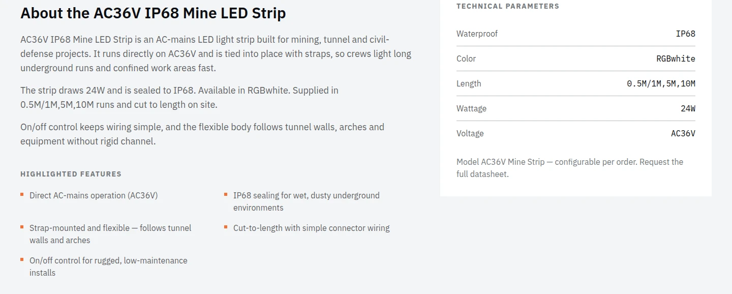
Above: what makes a curve workable — a strap-mounted flexible body that follows walls and arches, cut-to-length supply, and IP68 sealing on the completed run.
Every fixing point is a sealing boundary
A waterproof strip is tested as an assembly. The IP code is a classification of an enclosure against intrusion, and the second digit describing continuous immersion is defined against conditions the manufacturer states — so "IP68" is a claim about a tested assembly, not a property of the jacket material.
Underground, the assembly is modified at every cut, every connector and every place a strap crosses the body. Four habits keep the claim intact:
- Fix on the flat, seal at the ends. Ties and straps should not sit on a connector body or a cut end; they should sit on the extrusion, with the connector strain-relieved so the cable entry is not carrying the run's weight.
- Leave a drip loop at every feed. Water runs along a cable; a loop below the entry point gives it somewhere to go other than into the gland.
- Never crush the jacket to stop movement. A tie tightened until the extrusion deforms is a stress riser and a future leak. Use a defined fixing, or a clip sized for the profile.
- Re-verify after the field work. Whatever the factory tested, the completed run is a new assembly. The joint and re-sealing procedure is the part of the installation that decides whether the rating survives the first wash-down.
One boundary belongs with those four rules, because it is the one an installer is most likely to assume. IP68 addresses water and dust only. It is not an explosion-protection claim, and a sealed strip is not thereby acceptable in a classified or gassy location: there the model has to be the certified variant for that location, with the certificate, marking and scope approved against the area classification before the order — which is why a mine range carries purpose-built explosion-protected models alongside the standard ones. The fixing hardware is inside that boundary too. A stainless strap, a bracket or a junction box added on site is part of the assembly the approval covers, so the fixings have to come from the same approved system rather than from a site store.
The voltage side has one implication for mounting: on a long AC run the strip is fed at intervals, and each feed is a physical entry point and a fixing point at the same time. Where those intervals fall is an electrical decision, and it belongs on the same plan as the mounting rather than on a separate drawing issued a week later.
Access and re-mounting as the face advances
In a development heading, the lighting moves with the face. That single fact changes the mounting design: what looks like a permanent installation at commissioning is, six months later, a run that has been extended twice, re-tensioned once and partly relocated.
Design for it:
- Make the run extendable in factory lengths, with a joint at a reachable position every time the face advances.
- Keep a spare bay. A short loose section at the last fixing lets the run be re-tensioned without cutting.
- Hold spares as hardware, not just metres. Connectors and end caps are consumed at every field cut, and a spare drum of strip with no connectors is not a spare.
- Record the fixing schedule on the drawing, so the next crew inherits the interval and the method rather than inventing a new one.
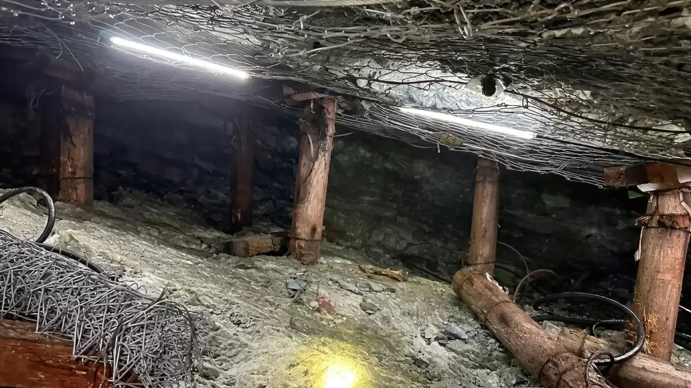
Above: the strip run along the back under the support mesh, tied to the support rather than to the rock — the arrangement that lets a heading extend the run as the face advances.
Maintenance access is the same argument seen from the other end: the joint that is unreachable is the joint that stays wet.
A mounting schedule you can hand to the crew
Everything above collapses into one table. Fill it per run, sign it, and issue it with the drawing.
# | Item | What to write |
|---|---|---|
1 | Section zone | Crown / spring line / haunch, with offsets from the surveyed line at each change of profile |
2 | Fixing method | Strapped to structure, catenary, or bracket — and which structure, named |
3 | Fixing interval | One number per zone, from the supplier's spacing table for the exact profile |
4 | Movement allowance | Where the expansion loop or slack bay sits, and how much |
5 | Factory lengths | Each length, its start and end chainage, and which ones cross a bend |
6 | Cut points | Every field cut, its legal interval, and the connector and end cap for it |
7 | Sealing | Method at each joint, who does it, and what is checked before energising |
8 | Access | How each joint is reached, and what spares are held on site |
Two rows carry most of the risk. Row 5 is where the curve gets paid for, and row 6 is where the electrical design and the geometry are reconciled. If either is blank, the crew will fill it in themselves, on the night, in the wet.
What the factory needs to quote the mounting package
A supplier can only design the fixing package if the request carries the geometry. What makes a quotation answerable is: the section drawing with the surveyed light line, the run lengths and total metres, the bend and section-change locations, the structure available to fix to, the ambient and wash-down conditions, and the points where feeds can enter.
The AC36V IP68 mine strip is built for exactly this kind of run: 24 W, AC36V, IP68, white or RGB, supplied in 0.5 m, 1 m, 5 m and 10 m lengths and cut to length on site, with a strap-mounted flexible body that follows tunnel walls and arches, and IP68 watertight connectors with end caps across the range. The wider mine LED strip range adds a 13 W/m heavy-duty tunnel strip and an impact-resistant model across AC36V, 48 V, 110 V and 220 V supplies, plus a flexible 100 LED/m version at 1,100 lm/m for routes that will not take a rigid profile. It is listed to CE, RoHS and BIS, MOQ is a single piece, delivery is quoted at 5–7 days and the warranty runs two years — the lines a procurement team checks before it reads the schedule.
What that looks like at scale is a 10,000 m AC36V delivery into a South African underground mine, where the strip threads along a timbered shaft and back under the support netting with minimal hardware — the mounting problem solved by tying to structure and keeping the joints reachable.
If the geometry is still on a drawing, send the section, the run lengths and the structures you can fix to, and ask for a fixing schedule rather than a box of clips. Pileds engineers will quote the strip, the connectors and the fixing kit as one package — which is the only version of the quotation that a crew can actually install from.
Specifying pixel LED for a real project?
Send the spec — pitch, IC, IP class, run length, voltage — and you get an engineer's answer, not a catalogue. Samples and OEM/ODM quotes from the Shenzhen factory floor.