
Facade Lighting Handover: Proof, Not Paperwork
A facade lighting handover is an evidence pack, not a folder: how to test measured lux, batch color match, IP joints, the DMX universe map and spares.
Facade lighting handover is usually treated as an administrative event: the installer hands over a folder, the consultant checks that the folder has the right tabs, and practical completion is certified. Six months later the color has drifted on one elevation, three segments are dead behind a gasket that was never seated, and nobody can tell which DMX address feeds the corner bay because the address spreadsheet was edited on site and never reissued.
The fix is not a longer document list. It is a different definition of done: every item in the handover package has to be a measurement you can repeat in front of the client, with a pass criterion agreed before installation and a result that points back to a specific fixture. This guide takes the six evidence layers of a pixel-LED facade — identity, light level, color, ingress protection, control mapping and the records file — and gives you the test, the instrument where there is one, and the evidence for each one.
If you are still at the design and specification stage rather than the commissioning stage, start with our facade and curtain wall lighting overview, which covers the design framework this article assumes is already fixed.
What a facade lighting handover has to prove
A handover package for a lit facade answers six separate questions, and each one needs a different kind of proof. Mixing them into a single "commissioning report" is where most disputes start, because a report that says "all fixtures operational and scenes verified" answers none of them.
Layer | The question it answers | Evidence that survives scrutiny |
|---|---|---|
Identity | Is what was installed what was specified? | Fixture schedule reconciled to as-built, with quantities and driver types |
Optical | Does the facade reach the agreed light levels, evenly? | Measured illuminance at a defined grid, with instrument and conditions |
Color | Do runs, elevations and batches match each other? | Chromaticity or ΔE data plus controlled photographs, per zone |
Ingress | Will it still be IP-rated after the joints were made on site? | IP certificate, factory test report, and a joint inspection record |
Control | Can someone else operate and repair it? | Universe/address map verified against physical fixtures, plus a config backup |
Records | Can a new contractor take over in five years? | As-builts, O&M manual, electrical test records, spares mapped to addresses, warranty start dates |
One verification sits underneath all six: electrical safety. Nothing in that table can be measured until the installation is safe to energize, and no part of the pack is more likely to be re-tested by a third party. Test each circuit dead first — protective conductor continuity from the board to the last fixture, insulation resistance between live conductors and earth — then live: the trip time of every residual current device protecting the run, and loop impedance at the far end. Record the readings per circuit against the as-built circuit list.
A circuit with no recorded result is not commissioned, whatever the scenes look like on the night.
Electrical verification is already a legal obligation in most jurisdictions and still the one most often missing from a facade file, because the electrical contractor's test sheets and the lighting contractor's O&M manual are assembled by two different people.
Identity comes first and gets skipped most often. Before anyone climbs a lift, reconcile what is physically on the building against the approved schedule — fixture variant, driver model, quantity, per elevation. Two things surface: substitutions made during procurement that nobody signed off, and shortfalls covered with a different variant from the same family. At handover they are a paperwork correction; two years later they are a color and spares problem with no paper trail.
Note what is missing: a list of scene names. Scenes are the client's operating preference, not evidence of installation quality — a beautiful opening-night show can still fail every layer above.
Lux on the facade: fix the measurement grid before the first night
Illuminance — lux — is the number on a facade contract most likely to be re-measured by a third party with a handheld instrument, so it is also the one most likely to be disputed. The dispute is almost never about whether the fixtures work; it is about where the readings were taken, with what, and under what conditions.
Three tests make it defensible.
Define the grid from the design intent, not from convenience. A wall-wash or grazing scheme has an illuminance target on a vertical surface: one point per structural bay per floor, plus the edges and corners where uniformity always dies. For a media facade the grid follows the module layout. Draw it on the elevation, number the points, and attach it to the acceptance plan. If the grid is invented on the night of commissioning, the installer will measure the bright center and the client will measure the dark corner, and both will be "right".
Control the conditions you can control. Exterior illuminance measurements are only meaningful after dark — daylight adds an unknown quantity to every reading, and it is not uniform across a tall elevation. Let the installation run at the test level for at least 30 minutes, then treat two consecutive readings inside the agreed tolerance as the stability test: a fixed waiting time proves nothing on its own, because junction temperature and driver output settle at different rates in a cold wind and a still summer night. Record the ambient conditions, the meter's calibration date, and whether the meter's receptor was held parallel to the surface being measured. Definitions for illuminance and luminance are standardized in the CIE International Lighting Vocabulary, which is also the reference to put in the report so nobody argues about what "lux" meant.
Report uniformity as well as average. A facade that averages the target while swinging 3:1 across a bay looks wrong even though the average passes. Record minimum, maximum and average for each zone and state the ratio explicitly — and say which ratio the contract uses, because min/avg and max/min are both common and they are not interchangeable. Declaring measurement uncertainty, rather than pretending a handheld meter is exact, is the difference between a report a consultant can sign and one they have to caveat; the JCGM guides on measurement uncertainty are the reference framework.
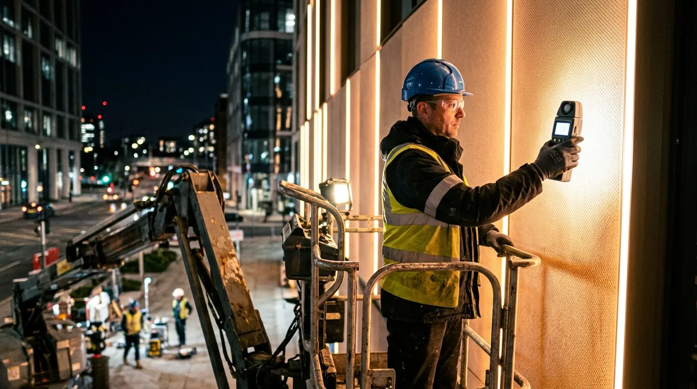
A single reading proves nothing on its own: what makes it evidence is the numbered grid it belongs to, with the point ID in the same frame as the meter.
Color match across runs and batches: chromaticity, not adjectives
Color is where pixel facades fail most visibly and where handover language is weakest. "Color consistent" and "matches approved sample" are not criteria; they are adjectives. A specifier needs a number, a measurement method and a sampling rule.
Start with the right metric. Correlated color temperature alone is not enough for white light, because two sources at the same CCT can sit on opposite sides of the Planckian locus and read greenish and pinkish next to each other. That offset is Duv, and it is the reason a nominal 4000 K facade can look patchy. For colored and mixed output, the useful metric is color difference — ΔE — computed in a defined color space; the underlying conventions are in CIE colorimetry. State in the acceptance plan which ΔE formula you are using, because ΔE*ab (1976) and ΔE00 (CIEDE2000) produce different numbers from the same two samples.
The second half of the problem is batch, not unit. LEDs are binned by flux and chromaticity, and each production batch has its own distribution inside those bins. A facade built from three deliveries can be perfectly within bin on every reel and still show a visible step where the batches meet. This is why the useful factory evidence is a per-batch test report, not a single type-test certificate: an integrating-sphere measurement of a sample from each batch, at the drive current the project uses, recorded against the same reference. We cover how binning codes and batch distribution actually behave in our guide to LED color consistency and binning.
On site, color evidence comes in two forms, and you need both — instrument readings that survive a challenge, and controlled photographs that match what the client sees.
Evidence | Instrument and method | Where to sample | What it proves |
|---|---|---|---|
Chromaticity / ΔE | Spectrometer or colorimeter, at the project drive current | First and last fixture of each run, every batch junction, one point per elevation | That the delivered light matches the agreed reference, in numbers |
CCT and Duv | Same instrument, white scenes only | Center of each white zone | Whether a white facade will read green, pink or neutral |
Photographic | Fixed white balance, ISO, aperture and shutter, raw files, marked camera positions | One frame per zone plus each batch junction, night only | What the client actually looks at, and a before/after reference |
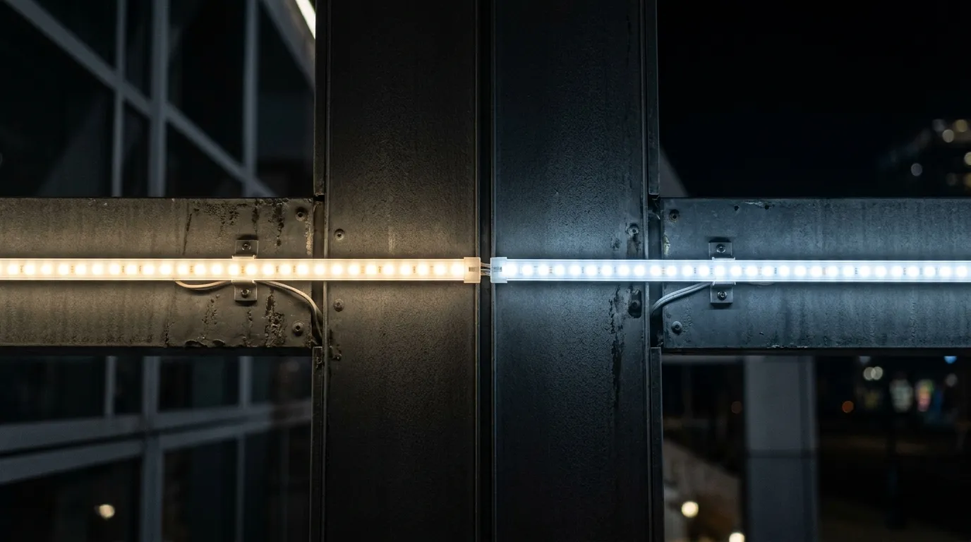
Warm white meeting cool white at a batten: a variant-level mismatch that needs no instrument to catch — the kind the identity check exists to stop. The batch-to-batch step is subtler than this — it shows up in large uniform fields, not in a close-up.
The pass criterion has to exist before installation. A common starting point for white-light facades is CCT within a stated tolerance, Duv inside a window of roughly ±0.003 to ±0.006, and a ΔE limit per zone taken from an approved mock-up. These are negotiating positions, not rules inherited from a standard; what matters is that they are written down, measured the same way, and signed off before the first reel is unspooled.
When a zone fails, there are only three honest remedies: swap the offending segments for units from the same batch as their neighbors, re-bin the run from the factory's remaining stock, or accept a documented deviation with the client's signature. Re-programming the controller to "fix" a color step does not work; it just moves the step.
IP evidence: the certificate proves the design, not the joint
An IP rating is a claim about an enclosure, tested under laboratory conditions. The IP code is defined in IEC 60529: the first digit covers solid objects, the second covers water, and the water digits mean specific tests — IPX6 is powerful jets, IPX7 is temporary immersion (typically 30 minutes at up to 1 m), IPX8 is continuous immersion under conditions the manufacturer states. The standard tells you what was tested; it does not tell you what happened on your building.
What actually fails on a facade is rarely the encapsulated body. It is the interfaces: the end cap that was crimped instead of potted, the connector that was mated with a grain of grit in it, the cable gland whose compression seal was overtightened until it bit through the jacket, the gland fitted without its sealing washer so the cable entry itself stands open, the junction box that collects water because it was mounted with its drain on the high side. Every one of those is created on site, after the certificate was issued — which is why the evidence for this layer has to reach the cable entry and not stop at the enclosure.
So the ingress layer needs three pieces of evidence, and only the first one comes from the factory paperwork:
- The IP certificate for the specific product family and rating — with a number you can check, not a logo.
- The factory IP test report for the test that produced the claim, plus the batch-level production checks the factory runs on sealing and potting.
- A joint inspection record from site: every connection type photographed, the potting or gasketing method recorded, and a sample of joints opened and checked. On exposed runs and coastal elevations, add a hose test on a completed section — with the client's representative present, because a hose test that nobody witnesses settles nothing.
The most common specification error here is treating the strip rating as the system rating. A genuinely IP68 pixel strip still terminates in a connector, a tail and a controller enclosure, and the assembly is only as sealed as its weakest interface; our comparison of IP67 and IP68 explains where the two grades diverge in practice. For the workmanship side — how a joint has to be made and potted to keep the rating it started with — see sealing LED strip joints on site.
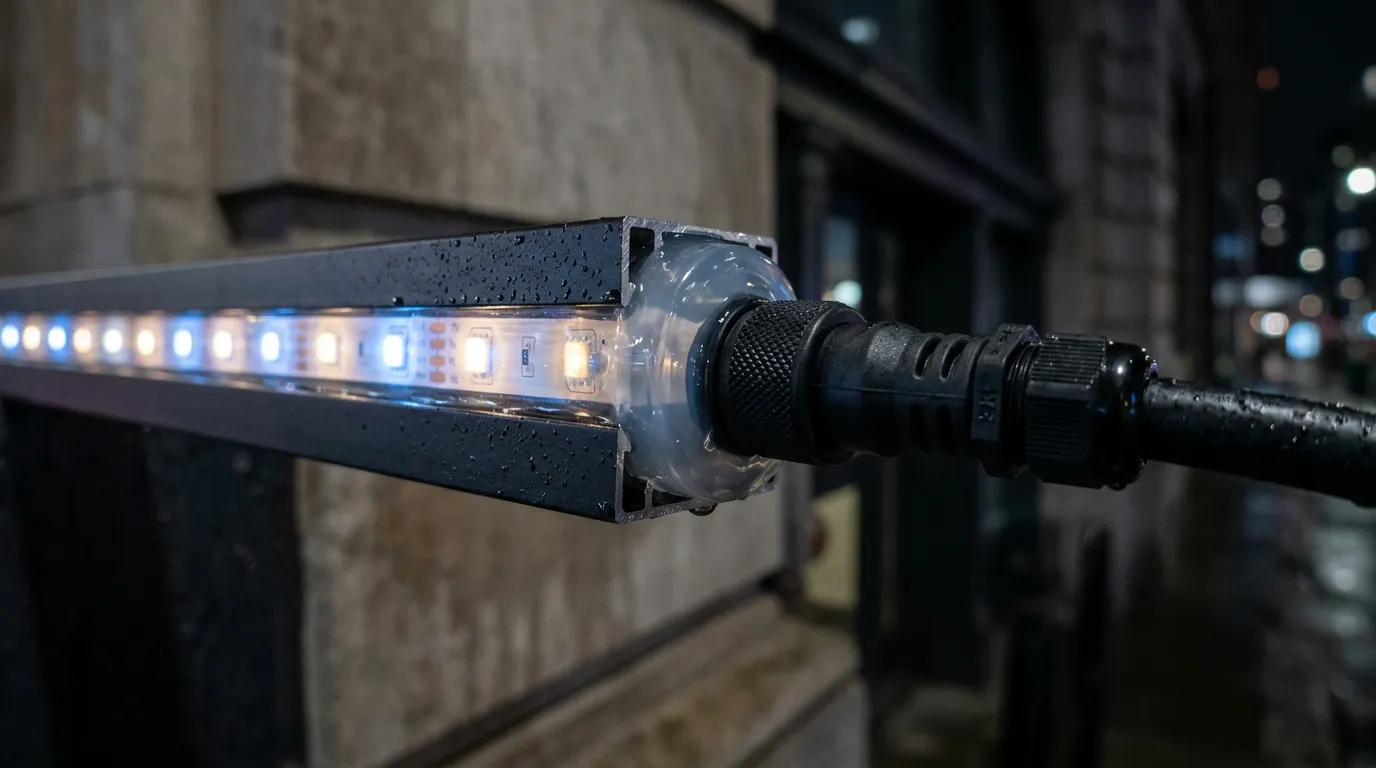
Potted end cap, cable gland, connector: the three interfaces that a factory certificate does not cover, because they are made on the building.
The DMX universe map is a testable document, not a spreadsheet
For an addressable facade, the control mapping decides whether anyone can maintain the installation after the commissioning engineer leaves — and it is the item most often delivered as an unverified export.
The arithmetic is where most "the last panel is dark" calls start. A DMX512 universe carries 512 control slots, as defined in ANSI E1.11. A fixture's footprint is the number of slots it consumes — typically 3 for RGB, 4 for RGBW, more if you are running 16-bit dimming or additional channels. Multiple fixtures share a universe until its slots run out:
last start address = 1 + (quantity − 1) × slots per fixture
If that result exceeds 512, the run has to break to the next universe and the map has to say so. Our primer on what a DMX universe is covers the slot arithmetic for a whole elevation. Over Ethernet the ceiling rises sharply — Art-Net carries DMX512 in UDP packets with a 15-bit port address, so the limit becomes the controller's port count and the network design rather than the cable. sACN (ANSI E1.31) lifts the same limit on networks that standardize on it, and the choice between the two is usually settled by the control software rather than by the fixtures; our sACN vs Art-Net comparison covers the practical differences.
A testable map has one row per addressable group, detailed enough for a technician who has never seen the project to walk up to the right fixture:
Field | Why it has to be there |
|---|---|
Zone and elevation | Where on the building, in the client's language, not the programmer's |
Fixture ID range | Links the row to the physical labels and to the as-built drawing |
Controller and output port | Which box, which port — the first thing checked in a fault |
Universe | The 512-slot block the row lives in |
Start address and footprint | Lets anyone recompute capacity without opening the software |
Power zone / circuit | Separates "no data" from "no power" in one glance |
Cable label | Lets a fault be traced to a physical run, not a guess |
Tested by, date, drawing revision | Makes the row a record rather than an intention |
Verification is physical, not digital. Import the map, then walk the facade: command each group individually, confirm the correct fixtures respond, and record any mismatch — including fixtures that respond to the wrong address and groups wired in reverse order along a run. Fix the map, not just the software, and re-issue it with a revision. Address-writer tools make re-addressing a run a fifteen-minute job instead of a lift-and-ladder afternoon. RDM, defined in ANSI E1.20, can speed discovery where every device and splitter in the path supports it — but never assume it does, and never let the map depend on it.
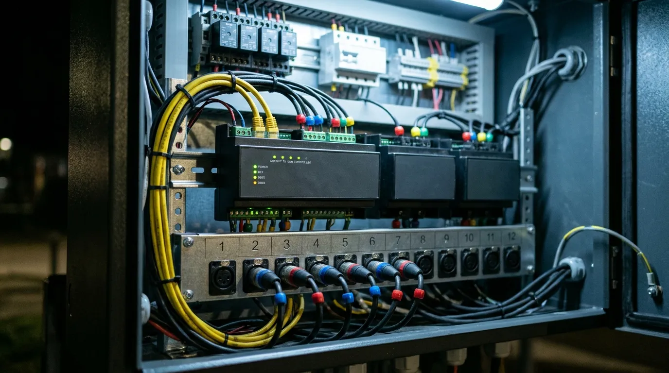
Numbered outputs and marked cables: the mapping is only as good as the labels a technician can actually read at 2 a.m.
Close the control layer with three files, not one: the as-programmed configuration export, a full backup with the software and firmware versions needed to open it, and the map itself as a controlled PDF. Store all three with the O&M manual and name an owner at the client's organization. A backup on the commissioning engineer's laptop is not a handover.
Spares, as-builts and the rest of the file
The remaining items are administrative, which is why they get deferred.
Spares. The usual starting point is 2–5% of installed quantity per fixture type, plus drivers and at least one controller per type. For pixel facades the number matters less than the mapping: spares should be labeled with the zones and address ranges they can replace, so a technician can pull the right unit without a color match on a lift at night. Hold spares from the same production batch where possible; a spare from a later batch can reintroduce the exact color step the handover was meant to close.
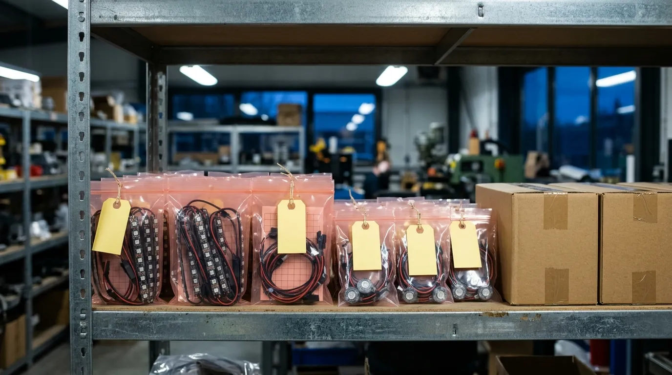
Spares bagged and tagged at packing: the tag is where zone, address range and batch code go, not just the part number — which is what lets a maintenance team match a replacement without re-measuring color on a lift.
Spare | Starting quantity | Must be mapped to | Kept where |
|---|---|---|---|
Fixture segments / points | 2–5% per fixture type | Zone, address range and batch code | Site store, tagged |
Drivers and power supplies | One per model, plus a working margin | Power zone and circuit label | Same cabinet or store, labeled |
Controllers / decoders | One per controller model | Universe range, plus the config file | With the O&M pack, not on a laptop |
As-builts. Drawings revised to show what was installed, not what was designed: actual fixture positions, cable routes, junction box locations, panel schedules, and every deviation marked, in editable and PDF form. The test is simple — hand the as-built to someone who has never been on site and ask them to find the junction box feeding the third-floor corner. If they can, it is an as-built; if they cannot, it is a design drawing with a new title block.
O&M manual. System description, operating procedures, scene and schedule documentation, fault-finding by symptom, maintenance intervals, spare parts list with part numbers, and the warranty start dates for fixtures, drivers and controllers — which are often three different dates. Add the training record: who was trained, on what, and when. Then test it the way you tested the as-built: give a technician the manual and a known fault, and see whether the manual alone gets them to the right component.
The power and data layout belongs in the same file, because most field faults are power distribution rather than control. If your facade runs long verticals with intermediate injection, the layout drawing from our curtain wall power layout guide is the shape the as-built should follow.
A handover sequence that fits the commissioning window
Commissioning a facade is constrained by darkness and lift access, so the sequence has to be planned rather than discovered. A workable order for a mid-size elevation:
- Before energizing — reconcile installed quantities and fixture IDs against the schedule; confirm the joint inspection record is complete. The pre-power-on commissioning checklist covers this stage.
- Power only — test each circuit dead and then live: protective conductor continuity, insulation resistance, the trip test on each residual current device, and polarity, at the source and at the far end of the run. Record the readings per circuit against the as-built circuit list.
- Control load — import the address map, run a full-white test, confirm universe boundaries behave (no group crossing from one universe into the next incorrectly).
- Channel test — R, G, B, W and dimming per zone; this is where swapped channels are caught.
- Address walk — command each group, confirm physical response, log mismatches.
- Scenes — run the approved static and dynamic scenes from the agreed viewing positions, not from the plant room.
- Optical measurement — illuminance at the numbered grid points, after the system has stabilized.
- Color measurement — instrument readings at the sample points plus the controlled photograph set.
- Fault and recovery checks — simulate a controller drop and a single fixture failure; confirm the system behaves as documented.
- Punch list and sign-off — every defect logged with a fixture ID, an owner and a retest date.
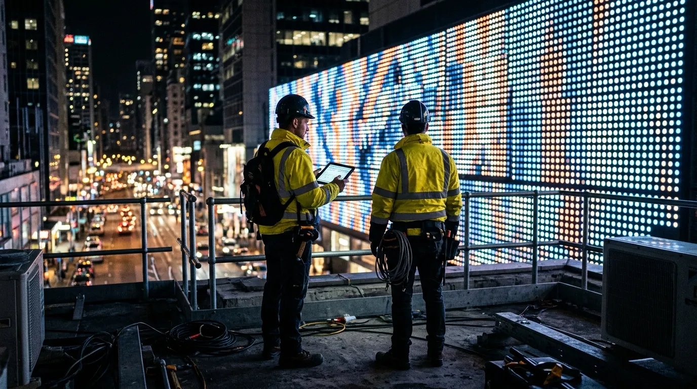
Commissioning happens in the dark and against the clock — which is why the sequence and the record templates have to be settled first.
Budget around two hours per layer for a single elevation of a few hundred fixtures — a long night plus a second pass, not one shift — and a tower with several elevations needs a week of nights.
The four failure patterns we see most often in acceptance reviews: readings with no grid definition, color evidence that is only photographs, an address map that was never walked, and spares with no batch or zone mapping. All four are cheap to fix before the night and expensive to fix after the retention release.
What to ask the factory for, and when
Most of this evidence originates upstream, and the cheapest moment to get it is the purchase order. Three items are worth writing into the supply contract:
- Per-batch integrating-sphere report at the project drive current, with the batch code traceable to the reels delivered.
- IP test report and sealing-process record for the exact product family and rating, plus the joint and end-cap method the factory uses.
- Address map template and controller configuration file in the format your commissioning team will use, delivered with the goods rather than reconstructed afterwards.
At Pileds the per-batch report is part of the production process: SMT, reflow, AOI, per-batch integrating-sphere checks on color point and luminous flux, then aging before packing — which is why the report can travel with the reels instead of being reconstructed months later. A wall-washer facade in Germany is one building those batch reports traveled with, from reel to finished elevation.
If you are writing a handover specification for an upcoming facade, send the elevation and fixture schedule to our team and we will map the factory-side documents against your acceptance layers.
Specifying pixel LED for a real project?
Send the spec — pitch, IC, IP class, run length, voltage — and you get an engineer's answer, not a catalogue. Samples and OEM/ODM quotes from the Shenzhen factory floor.