
Outdoor Pixel Strip Connectors: 4 vs 5 Pin
Waterproof connectors for outdoor pixel strip: what 4 pins and 5 pins actually carry, why addressable RGBW needs three, and what keeps a wet joint dry.
Four pins or five? On waterproof connectors for outdoor pixel strip, that question has a right answer — but it is not the answer most buyers expect, and even the right answer leaves untouched the part that actually fails outdoors.
Pin count is a carrier map. Four conductors carry analog RGB, or data with a clock, or data with a backup line. Five carry analog RGBW. That is all the count tells you. It does not tell you whether the shell will mate with the connectors already on site, whether the joint will still be dry in year three, or whether the current for your run will fit through the contacts inside it.
And most addressable strip runs on three. WS2811, WS2812B, SK6812, WS2814, UCS1903 — three conductors, whatever colors the strip produces. So when a supplier offers a five-pin "pixel" connector, one of two things is true: you are being sold an analog RGBW part wearing the word pixel, or you are looking at a vendor dialect you will not be able to buy again in two years.
We build sealed and addressable strip in Shenzhen and ship it into facades, signage and shows. The returns that cross our bench are rarely a failed LED. They are a connector that let water past the pin field, or a pin field that corroded until the far end of the run went amber and everyone blamed the power supply.
Count the conductors before you count pins
The two families in the table below grow differently. On analog strip every color needs its own return, so the count climbs with the number of channels. On addressable strip a single data wire carries the whole color value, so four channels can travel down three wires. Once you know which family is in your hand, half the pin-count question is already answered.
Conductors | What they carry | Strip family | Typical IC or part |
|---|---|---|---|
2 | V+ and ground | single color | — |
3 | V+, ground, data | single-wire addressable RGB | WS2811, WS2812B, UCS1903, SM16703 |
3 | V+, ground, data | single-wire addressable RGBW | SK6812, WS2814, TM1814, UCS2904 |
4 | common V+ with red, green, blue | analog RGB | 5050 RGB |
4 | V+, ground, data, clock | clocked addressable | APA102, SK9822, WS2801 |
4 | V+, ground, data, backup data | addressable with redundancy | WS2815, WS2813 |
5 | common V+ with red, green, blue, white | analog RGBW | 5050 4-in-1 |
6 | common V+ with RGB and two whites | analog RGBCCT | 5050 5-in-1 |
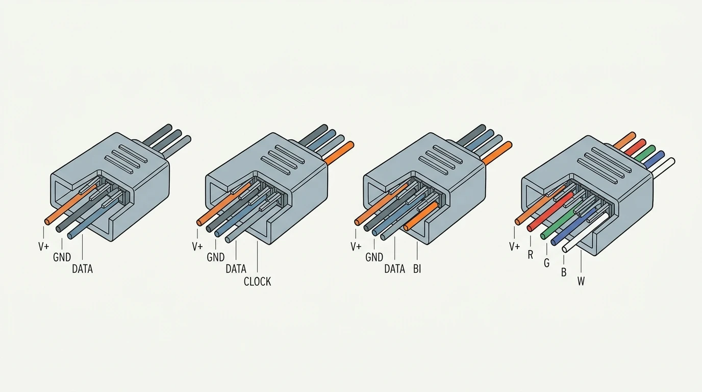
Two conductors is single color only — no data line, no color mixing — and it shows up in a pixel order because installers buy everything for a site on one purchase order, not because a pixel run needs it. The row that matters is the next one: a pixel strip wired for a 3-pin connector is the normal case. Note that it appears twice, once for three-channel parts and once for the four-channel parts that keep the same three wires — which is the subject of the next section.
The 4-conductor row repeats three times, and that is the worst ambiguity in this corner of a catalog. Three different electrical jobs share one shell type, and from the outside the connectors are indistinguishable. Get the pairing wrong and the three mistakes fail in three different ways. An analog RGB strip wired to a clocked output lights, in the wrong colors, because each channel return is being driven with something that is not a channel value. A clocked strip plugged into a backup-data strip also lights, and looks correct — until the first pixel dies, at which point the redundancy that strip was bought for is not there, because the backup line was being fed a clock instead of a copy of the data. And in the third case the mismatch is controller-side rather than strip-side: an analog controller's switched channel output landing on an addressable strip's data input puts twelve or twenty-four volts into a logic input, which is how driver ICs die — quietly, at the far end, rather than at the joint.
So count the pads on the strip under the silicone, not the pins in the bag. Three pads means a 3-pin connector, whatever the listing calls the product. Four pads means you need to know which four before you order a 4-pin LED connector, because "four-pin" on its own has just stopped being an answer.
Read the IC, because five pins rarely means what the label implies
Pin count gets read as channel count, and on analog strip that reading holds. Add a driver IC and it stops holding: an addressable strip can produce any number of channels from a single data wire, so the count no longer tracks the colors.
Four-channel addressable parts are still three-conductor. WS2814, SK6812, TM1814 and UCS2904 carry all four channels down one data line. White is a fourth value in the data stream, not a fourth wire. A 5 meter length of 12 V RGBW pixel strip built on one of these is a three-conductor part, and a five-pin connector bought for it arrives with two pins that have nothing to connect to.
Where a fourth conductor does appear, it is usually not a clock. WS2815 and WS2813 add a backup data line so that one failed pixel does not blank everything after it. APA102 and SK9822 add a real clock line, because they latch on it. Both are four-conductor strip; neither is interchangeable with the other, and neither is a five-pin part. Feeding a backup-data line from a clock output is the kind of mistake that costs an evening, because the run usually lights and does the wrong thing.
Five conductors means analog RGBW, nearly without exception. A common positive with a switched return for red, green, blue and white. It is a sound product. It is simply not addressable, and it is not what most buyers mean when they ask for a 5-pin LED strip connector.
There is a second five-pin object in this trade with nothing to do with strip channels: 5-pin XLR, the usual connector for DMX512 cable. The five conductors there are the shield, the primary data pair and an optional second pair — not a color count, and it does not appear on a strip pigtail.
The instruction is one line long: before you accept any pin count, ask for the pinout drawing. A factory that builds these parts produces one in ten minutes — conductor, function, color, pin number, in a table. A trader who cannot is telling you something more useful than anything on the listing.
Judge the seal on the mated pair, not on the part
Everything above is electrical. The outdoor question is mechanical, and it starts with what an IP number is attached to. A waterproof LED strip connector is a part number. What keeps water out of the run is an assembly, and the part number is only one of its three elements.
The code comes from IEC 60529, and the second digit is the water test. The IEC's own explainer is direct about why the standard exists: to replace marketing words like "waterproof" with a specific, repeatable test.
The test conditions behind each digit are where a connector specification usually goes wrong.
Code | Test condition | What it reads as on a pigtail |
|---|---|---|
IPX5 | 6.3 mm nozzle, 12.5 L/min, 30 kPa at 3 m, 3 min | Rain driven hard at the joint under wind |
IPX6 | 12.5 mm nozzle, 100 L/min, 100 kPa at 3 m, 3 min | A pressure washer aimed at the joint |
IPX7 | Immersion 1 m, 30 min, lowest point 1,000 mm below the surface | A joint sitting in a flooded trough |
IPX8 | Continuous immersion, depth and duration agreed with the manufacturer — no fixed numbers in the standard | A joint in a sump, or wherever a project spec names a depth |
On a product page the water digit usually arrives attached to a dust digit — IP65, IP66, IP67, IP68 — and the pair is read in that order. The first digit is a dust and solid-object question, which is maintenance; the second is the water test, which decides whether the assembly survives the site.
Here is what a datasheet cannot say. The rating belongs to a specimen in a fixture at a factory. A molded pigtail is rated as a complete assembly: gland closed on the jacket, mating face closed by its mate or its cap, no load on the cable. The joint a technician closes on site is a different assembly with a different history — two shells of a screw-lock (threaded-nut) connector, an O-ring, and however far a nut got turned in the rain. Two IP67 halves do not make an IP67 joint. They make an untested joint, and it is the only element of the run with no test evidence behind it.
Which is why the useful questions are not "what is the rating of this IP68 connector" but four others:
- What is the rating of the mated pair, and which condition was tested — jet, or immersion?
- Who tested it, on what assembly, with the cable and the cap in place?
- Is there a tightening specification: torque, or turns past hand-tight?
- What closes the half that is not plugged into anything?
Answer those four and the pin count matters less than you would think. Answer none of them and an IP68 label on the shell is decoration. Whether IP65, IP67 or IP68 is appropriate for a given exposure is a separate decision, and the IP65 versus IP67 comparison covers the two grades that come up most on strip.
The environment side — salt, sun, freeze-thaw, washdown — is in the outdoor IP selection guide.
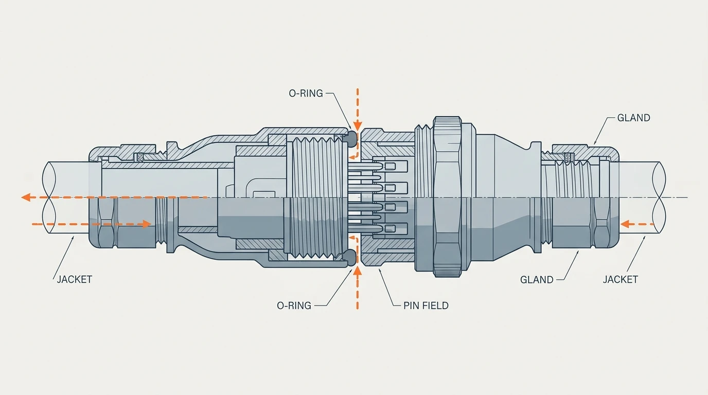
Six ways a waterproof connector for an outdoor pixel strip still fails
Leaks do not distribute evenly across the possible causes. They cluster, and none of the clusters is visible in a pin count.
Condensation, from the inside. A sealed connector body is a small trapped air volume. It warms by day, cools at night, and the vapor inside condenses on whichever surface is coldest first — on a metal shell, usually the shell itself. Droplets then run to the lowest point, which is the pin field. A joint can pass a jet test in a factory in July and deliver a wet pin field in February without a drop of rain entering from outside. Nothing has failed a rating; a sealed volume has simply done what sealed volumes do.
Corrosion under DC bias. Twelve or twenty-four volts across a damp pin field is an electrolytic cell, and the positive contact is the one that gives up metal. Add chloride from coastal air and the deposit that appears is the green crust you find when the joint is opened in year two — a corrosion product, not dirt, and it does not clean off. Resistance climbs slowly, then quickly, and the symptom shows up at the far end of the run rather than at the joint that caused it.
Water travelling the jacket. A gland seals where it grips the jacket. Water running down a vertical cable reaches that grip from above, and if the jacket is scuffed, porous, or not fully inserted, it goes inside the gland rather than around it. This is, in our experience, the most common real leak on outdoor lighting: not a failed seal, but a seal that was never asked to stop water arriving from that direction. The remedy is geometry, not a higher IP digit — enter from below, and hang a drip loop under the entry.
Strain, not water. A connector that carries its own cable weight is under load every time the run moves: thermal expansion, wind, someone lifting a length. The pin field is the weakest mechanical element. A pin that has backed out of its housing can still make contact on the supply pair while the data line opens, and a run with power and no data looks exactly like a dead output — which is why the controller gets swapped twice before anyone inspects the joint.
UV, on a three-year clock. Shells yellow and embrittle, seals harden and take a set, and a south-facing facade at year three is not the part that was tested at day three. Black shells hide the yellowing and run hotter while they do it.
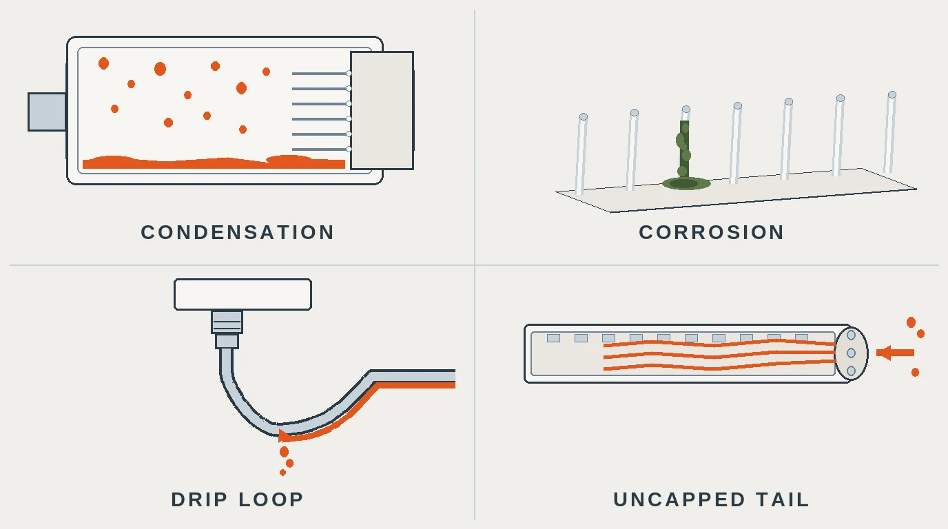
The plate above shows the four that a camera can catch: condensation inside a sealed body, corrosion on a pin, the drip-loop remedy for water arriving down a jacket, and the uncapped tail covered at the end of this section. Strain and UV are not visible on a bench — one shows up as data that stops partway along a run, the other as a shell that cracks when it is touched in year four.
The sixth failure is the cheapest to prevent: an unused tail with no end cap. An unterminated strip end is an open tube. Water enters the cut face, wicks along the conductors, and arrives inside the first sealed joint from the wrong direction entirely. Cap it, pot it, or order the length you actually need.
None of these is fixed by adding a pin, and none is prevented by a higher IP digit on the shell. They are fixed by the assembly design, the termination method and the specification — the subject of the next four sections.
Size the contact, not the pin count
Every color arrangement funnels into the same bottleneck. At the feed point, one contact carries the total current of the run, and the number of pins does not change that.
Put numbers on it. Five meters of 24 V RGBW strip at 19.2 W/m is 96 W, which is 4 A at the feed. Five meters of 12 V RGB strip at 14.4 W/m is 72 W, which is 6 A. Either way the whole of that current passes through one V+ contact pair, whether the shell carries three pins or five; on analog parts the return current splits across the channel returns instead of a single ground.
What the copper does with it, from the wire gauge tables: 22 AWG copper is about 52 mΩ per meter, 20 AWG about 33 mΩ, 18 AWG about 20 mΩ. A 0.4 m 22 AWG pigtail is therefore roughly 21 mΩ per conductor. At 6 A that is about 250 mV across the pair, round trip — a voltage drop of about 2% on a 12 V run, and unremarkable. The catch is ampacity rather than drop. For insulated conductors in a bundle at 60 °C, published ratings for 22 AWG sit near 3 A, so a 6 A feed is already past the conductor's limit at a length where the meter would look perfectly acceptable. That is why the rule below is 20 or 18 AWG above about 4 A, and why the drop figure alone never clears a conductor.
Now let the joint corrode. A damp pin field does not raise resistance by ten percent; an order of magnitude is the realistic order. The same pigtail at the same current then costs a fifth of the supply voltage, and the symptom is a run that is bright at the controller and amber at the end. That failure mode is covered in diagnosing a dim end on site, and it is routinely blamed on an undersized supply because the joint measures fine when the meter is on the copper and not across the mated pair.
Three consequences for the 4-versus-5 decision:
- Pin count buys channels, not current. A five-pin analog RGBW part puts the sum of four channels on one common contact. The pin count gives the feed contact no relief in either family — the five-pin part simply has no spare conductor to share it with.
- Gauge belongs on the purchase order. Specify 20 or 18 AWG on the power conductors for feeds above roughly 4 A, and state it per conductor rather than "suitable cable". Pigtails that look identical at the nut come in 18, 20 and 22 AWG.
- The feed point is a design decision, not a detail. Feeding a long run from both ends halves the current per contact, which is almost always cheaper than the next gauge up. The arithmetic for that is in sizing a power supply for pixel strip.
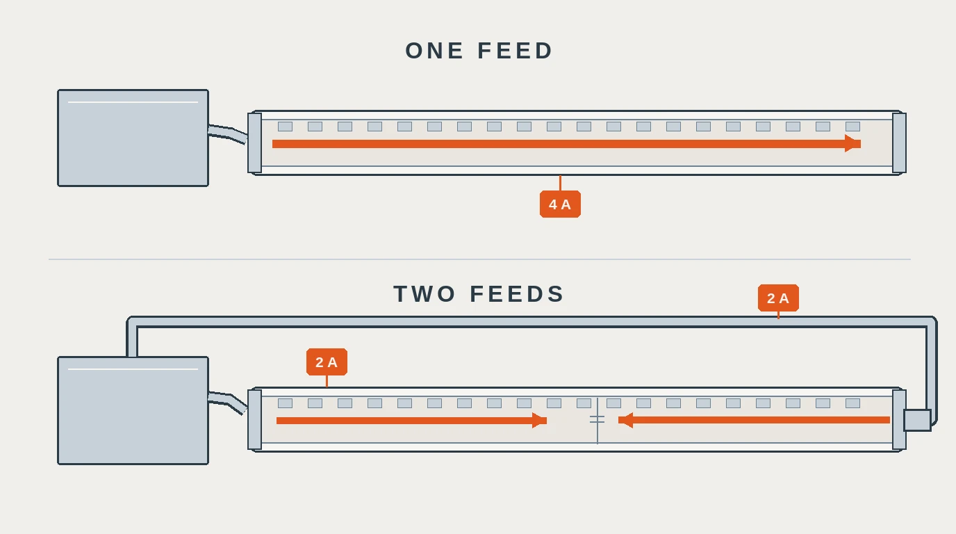
Standardize one connector family across the project
The connectors sold for pixel strip are not one standard. There are three or four de-facto families — the screw-lock, threaded-nut form a buyer will recognize instantly — that look alike, sit within a few millimeters of each other across the nut, and do not mate with each other. None of them is a registered standard of the kind that governs industrial M12 connectors, which is why a specification cannot simply cite one by number.
The families have names installers use even where no standard exists — Ray Wu and xConnect are the two a buyer is most likely to meet — and none of them is intermateable with the rest.
A forced joint is worse than a loose one. The threads are close enough to start and the notch close enough to misalign, and what gives way is the pins inside — a bent pin cannot be straightened in the field, so the cost is a replacement part and a second trip up the structure.
For one install that is annoying. For a project, a distributor's line, or a service contract it becomes an inventory decision:
- One family per project, stated in the documentation. Every pigtail, extension and cap from the same family, so a technician in year two cannot create a mismatch by reaching into the wrong box.
- An adapter is not a solution, it is a new interface. It adds two seals where the drawing specified one, a part that has to be stocked in both directions, and a failure point nobody planned for. Tolerable at one or two seams; wrong as a system.
- Spares belong in the same order. Capped spare pigtails at a few percent of run length, plus end caps, in the specified family, held on site. A spare in the wrong family is a spare that gets forced.
- Publish the pinout. One table on the project documentation: conductor, function, color, pin number. That ends the wire-color argument permanently, because vendor color codes do not agree with each other.
The rest of the decisions around power supplies, profiles and terminations for a pixel install sit in the pixel LED accessories guide; this article is the connector slot in that set.
Write the connector specification into the PO
Everything above collapses into seven clauses. They are written to be pasted into a purchase order or a submittal, and each one exists because its absence has a specific failure attached.
Clause | What to write | Why it is there |
|---|---|---|
Pinout | "Pinout per drawing: conductor, function, color, pin number. Drawing to be issued with the order acknowledgement." | Removes wire-color disagreement and makes a repeat order actually repeatable |
Conductor count | "Conductor count to match strip: 3 for single-wire addressable (WS2811/WS2812B/SK6812/WS2814), 4 for WS2815 or APA102-class, 5 for analog RGBW." | Stops the fourth and fifth conductor being bought by habit |
Sealing | "Mated-pair rating IP67 or IP68 (state which), tested to the corresponding IEC 60529 water test; test method and testing party to be stated; cap supplied for each unused half." | The rating that matters is the assembly's, not the shell's |
Current | "Contact rating to be stated in amps per contact; power conductors 20 AWG minimum; power injection points as drawing." | The feed contact carries the sum, regardless of pin count |
Keying | "One connector family throughout; non-intermateable with other families; nut size and notch profile stated." | Prevents the forced joint that breaks pins |
Strain relief | "Cable gland to grip the jacket; cable supported independently of the connector; 150 mm service loop at each joint." | Stops the pin field being the mechanical fuse |
Spares | "Capped spare pigtails at 5% of run length; end caps for every unused tail; all in the specified family." | An uncapped tail is an open tube, and a wrong-family spare is a forced joint |
If a supplier cannot draw the pinout, they cannot build it twice. The drawing is not paperwork; it is the only artifact that survives a change of shift, a change of buyer, or a change of factory.
Terminate the joint so it stays dry
The sequence matters more than any individual step, because two of these are impossible once the run is at height.
- Cut at a cut line, and count pads first. A 4-pad strip cut to suit a 3-pin pigtail has just lost its clock or its backup line. Cutting mid-segment leaves copper that no seal covers properly.
- Terminate with a factory-molded end. A solderless clip holds the pads by contact pressure alone, which is exactly what a season of thermal cycling and wind removes. Molded ends are part of a tested assembly; a clip is a joint with no test behind it.
- Put the joint where water leaves, not where it collects. Cable enters from below where the geometry allows, with a drip loop under the entry. A joint at the low point of a run is a joint in a puddle.
- Seal the assembly, not the pin field. The O-ring that came with the connector is the seal; silicone added to the mating face can hold the nut off its seat and defeat it. Dielectric grease on the contacts is a corrosion barrier, not a waterproofing step, and it has to be compatible with the elastomer.
- Test the assembly, not the part. Insulation resistance before and after a wet test on the finished joint, recorded. A number that changes is the evidence; a number that is merely high is not.
- Cap every tail, including the spare. An unused end is an open tube for the life of the installation.
One boundary before any of this goes into a scope of work: supply voltage, overcurrent protection, grounding and the wiring method are the installing electrician's scope rather than the connector's, and nothing in this sequence substitutes for a compliant site supply.
Where a run has to be joined in the field rather than terminated at the factory, that is a different craft with its own failure modes — sealing a cut strip end so the IP rating survives — and the honest framing is that a factory termination is part of a tested assembly while a field joint is not, however carefully it is made.
When five pins is the right answer
Analog RGBW is a legitimate specification, and the five-conductor connector that goes with it is the correct part in three situations.
You need a white that is not a mix. A dedicated white die gives a cleaner white and a more predictable CRI than three channels approximating it, which matters on signage and retail frontage where white is the brand color.
You are dimming in analog, per channel. Analog RGBW on a constant-voltage controller is simple, cheap, and indifferent to protocol, refresh rate and pixel mapping. For a static accent run it is the shorter path to a working installation.
You are running analog RGBW over a long span at 24 V. Twenty-four volts halves the current for the same wattage, which buys run length before injection; the arithmetic for that is in the contact-sizing section above. Note what is doing the work there: the voltage buys the run length, and the fifth conductor buys the dedicated white. Neither substitutes for the other, and 24 V on a three-conductor addressable strip is a perfectly normal specification.
What five pins is not is a route to addressable RGBW. For that, the catalog offers the other answer: an IP68 addressable RGBW strip at 60 LED/m, DC12V, cuttable every three LEDs and shipping in IP20, IP65, IP67 or IP68 — an addressable RGBW part whose sealing class you choose at order rather than inherit from a connector label. If the reason you were considering five pins was "RGBW with pixels", that is the configuration to compare against, and the mated-pair question from earlier applies to whatever termination you specify with it. One caution before you read that page: its product name carries a driver-family name that predates four-channel versions of the part, which is exactly the vendor dialect this article opened with. Ask for the wiring drawing rather than reading the name as a channel count.
FAQ
Do all LED strip connectors mate with each other? No, on two independent counts. Conductor count decides what a connector carries; keying decides whether two parts will join. Three-conductor pigtails from different families carry identical signals and still will not screw together.
Will a 4-pin connector work on a 5-pin strip? Not usefully. The fifth conductor has to go somewhere, and in analog RGBW it is a color channel — leave it unconnected and one color never lights. Check the strip before ordering a replacement pixel LED connector: four-channel addressable parts are three-conductor, and a 4-pin part may already be the right one.
How do I know which pin is which? From the drawing, or from the pads printed at the cut line — not from wire colors, which differ between vendors. Data also has a direction: the input end of the strip is the end the controller has to drive, and a run wired backwards stays dark in a way that looks like a dead output.
Do I need five pins for RGBW? Only for analog RGBW. Addressable RGBW on SK6812, WS2814, TM1814 or UCS2904 runs on three conductors, and WS2815-class strip runs on four with a backup data line rather than a white channel.
Send the run length, the IC, the voltage, the IP class and where power enters, and we will confirm the conductor count and the termination arrangement before you commit to an order — including the end caps, which is the line most connector orders are missing. Low minimum order quantities, and samples for qualified projects. Send the project details and the answer comes from an engineer rather than a catalog.
Specifying pixel LED for a real project?
Send the spec — pitch, IC, IP class, run length, voltage — and you get an engineer's answer, not a catalogue. Samples and OEM/ODM quotes from the Shenzhen factory floor.