
LED Point Lights for Facades: Spacing and Addressing
How to space and address LED point lights on a facade: viewing distance to node pitch, DMX universe and SPI data limits, and where the power zones fall.
What "LED point lights" means on a facade
LED point lights are single addressable nodes — one lens, one driver chip, one address — used in arrays across a building facade to build a dot grid, an image or a contour. On a media facade the node is the pixel, and the two drawings that decide the project are the node spacing and the address map.
Suppliers quote the same parts as addressable LED point lights, LED pixel point lights, or simply LED dot lights. They are not a path light and not a strip: on a facade, and in media facade lighting generally, the node is the pixel, and the drawing that reaches the controller is the address table behind it.
That definition is doing more work than it looks, because "led point lights" is searched by at least four different people. One wants low-voltage garden fixtures. One is a photographer looking for a single-point studio lamp. One is looking for a Danish lamp brand whose name contains the words. Only the fourth — the specifier laying out an addressable grid on a building — is who this article is for. Everything below assumes that fourth reader: nodes on a facade or curtain wall, each one individually controllable, driven over DMX512 or Art-Net or over SPI from a pixel controller.
If your spec is still at the scheme level — light levels, glare, colour temperature, how the building should read at night — that work belongs to facade lighting design and specification.
This article is one layer down: the node, the grid it sits in, and the addresses that reach it. It belongs inside the facade and curtain wall lighting guide, which holds the wider framework.
The short version for anyone who needs it in one paragraph: point-light spacing on a facade is set by the distance the viewer stands at, not by what the fixture can do; the node count that spacing produces is what determines your load, your DMX universes and your data lines; and every node needs a unique address, which means the grid you draw is also an address table — get the two out of step and the show runs, but not the way it was rendered.
Spacing starts with the distance the viewer stands
Point light spacing is usually quoted as a range — "50 to 500 mm grids are common" — and that is true and useless at the same time. The range exists because spacing is a function of viewing distance first and a design decision second.
The physics is angular. Normal vision, 6/6 or 20/20, resolves two points separated by one minute of arc — that is the definition used in the international acuity standard, equivalent to 60 pixels per degree, and the eye's own optical limit is finer still at around 28 arc seconds (visual acuity). One arc minute works out to a separation of roughly 0.29 mm for every metre of viewing distance: at 20 m, two points 5.8 mm apart are still distinguishable as two points.
The industry rule of thumb is much looser than that. "Minimum viewing distance in metres ≈ pitch in millimetres" is a 1:1000 relationship — an angular separation of 3.44 arc minutes, or about 3.4 times the 20/20 limit. That factor is the whole point: a facade designed right at the acuity limit is one where the audience can see every individual node and every gap, with zero margin for a viewer with better than average eyesight, a camera with more resolution than an eye, or a photograph that will be examined at leisure.
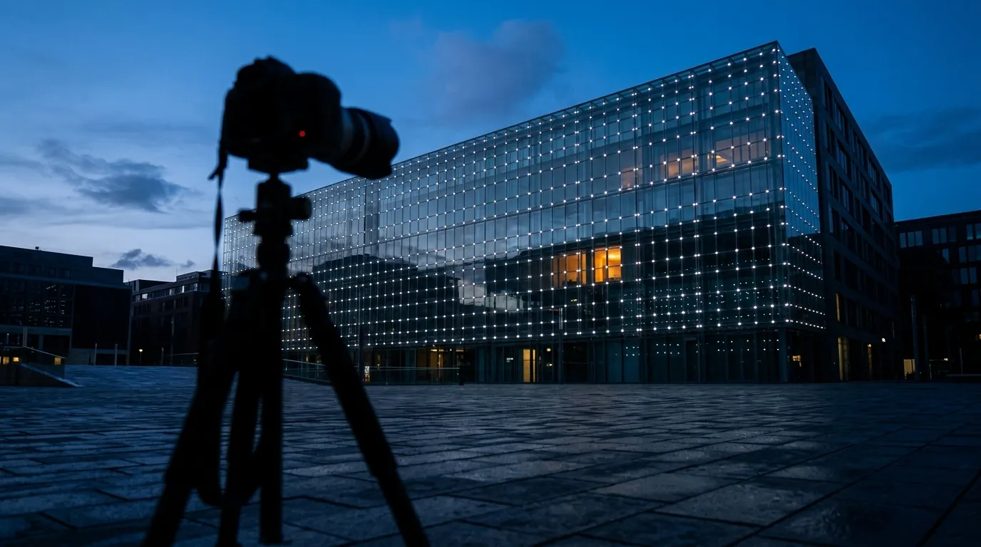
The viewer is part of the specification. Design to the distance the camera will stand at and the pitch decides itself; design to the distance you hope people stop at and the grid fails the first photograph.
Design to the distance the camera will be, not the distance you hope people stand:
Viewing distance | At the 20/20 limit | At the 1:1000 design rule | At the eye's own limit |
|---|---|---|---|
10 m | 2.9 mm | 10 mm | 1.4 mm |
20 m | 5.8 mm | 20 mm | 2.7 mm |
30 m | 8.7 mm | 30 mm | 4.1 mm |
50 m | 14.5 mm | 50 mm | 6.8 mm |
100 m | 29.1 mm | 100 mm | 13.6 mm |
Read the table as a budget, not a menu. The middle column is the spacing at which a grid starts to read as a continuous surface from that distance; go finer and you are buying resolution the viewer cannot fully use; go coarser and the facade reads as a dot matrix from the sidewalk even though it looked smooth on the render. Broadcast and photo documentation is usually shot closer than the design viewing distance, which is why colour-critical and camera-facing grids are specified at the fine end of the range.
Two refinements matter in practice. First, the pitch is not uniform in effect — a 300 mm grid viewed at 60 m and a 100 mm grid viewed at 20 m resolve to the same thing, so the useful question is never "what pitch?" but "what pitch at what distance?". Second, content drives tolerance: a slow colour sweep survives a coarser grid than a logo or a face. If the content is abstract, you can widen the spacing and spend the money elsewhere; if the client has ever shown a video, assume they will.
The pitch you choose sets node count, load and universes at once
Here is the arithmetic that turns a spacing decision into a procurement decision. Density is the reciprocal square of pitch, and every number downstream inherits it.
Pitch | Nodes per m² | Load at 1.68 W per node | Area covered by one RGB universe (170 nodes) |
|---|---|---|---|
500 mm | 4.0 | 6.7 W/m² | 42.5 m² |
400 mm | 6.2 | 10.5 W/m² | 27.2 m² |
300 mm | 11.1 | 18.7 W/m² | 15.3 m² |
200 mm | 25.0 | 42.0 W/m² | 6.8 m² |
100 mm | 100.0 | 168.0 W/m² | 1.7 m² |
50 mm | 400.0 | 672.0 W/m² | 0.4 m² |
The 1.68 W figure is a real node-class number — it is the rated full-white consumption of a 50 mm coin-type node, the size most facade grids use. Substitute your own node's rating and the load column changes; the shape does not.
That shape is the trap. Halving the pitch does not double the node count, it quadruples it — and it quadruples the load, the fixture count, the number of holes or clips, the number of addressable points to commission, and the number of things that can fail 30 metres off the ground. A facade that is 11 nodes per square metre at 300 mm becomes 100 nodes per square metre at 100 mm. Nobody looking at a render sees a 9× cost difference; everybody signing the purchase order does.
The last column is the bridge to the control layer, and it is the number most often left out of a facade package. At 300 mm, one DMX universe of RGB nodes covers about 15 m² of elevation. At 100 mm, one universe covers 1.7 m². On an RGB point-light facade the spacing decision has already decided how many universes, how many controller ports and how many data runs the job will need — before anyone opens a control console.
Snap the grid to the building, not to a round number
A theoretically perfect grid is a drawing problem; a real grid is a construction problem. The elevations that survive contact with site are the ones aligned to something the building already has.
Align to the module, then round the pitch. Curtain wall panels, mullion centres and floor heights give you a repeating module. A pitch that divides the panel width or the mullion spacing evenly produces a grid that looks deliberate at every edge. A pitch that does not produces half-nodes at panel joints, and half-nodes are where a facade starts looking like a mistake. Work backwards: pick the pitch from viewing distance (previous section), then adjust it — usually by a few millimetres — until it lands on the module. Then check the node count and the universe count again, because both have just changed.
Design the edge zone deliberately. Nobody specifies a facade that runs to the physical perimeter of the cladding. There is an inset — typically one panel or one mullion bay — where the grid stops and the lighting either fades or is omitted. Decide that inset explicitly and dimension it on the drawing; leaving the edge to site judgement is how a building ends up with a bright line of dots running into a gutter.
Carry the tolerance stack on the drawing. Node placement tolerance, panel fabrication tolerance and mullion installation tolerance add up. If each is ±3 mm, the worst-case node in a large grid can be 9 mm off its nominal position, and the eye is very good at spotting a locally uneven dot grid even when it cannot see individual nodes. The remedy is the same at every scale: specify a placement tolerance that is a fraction of the pitch — a common starting point is ±10 % of pitch — and make the installer responsible for the cumulative rather than the individual case.
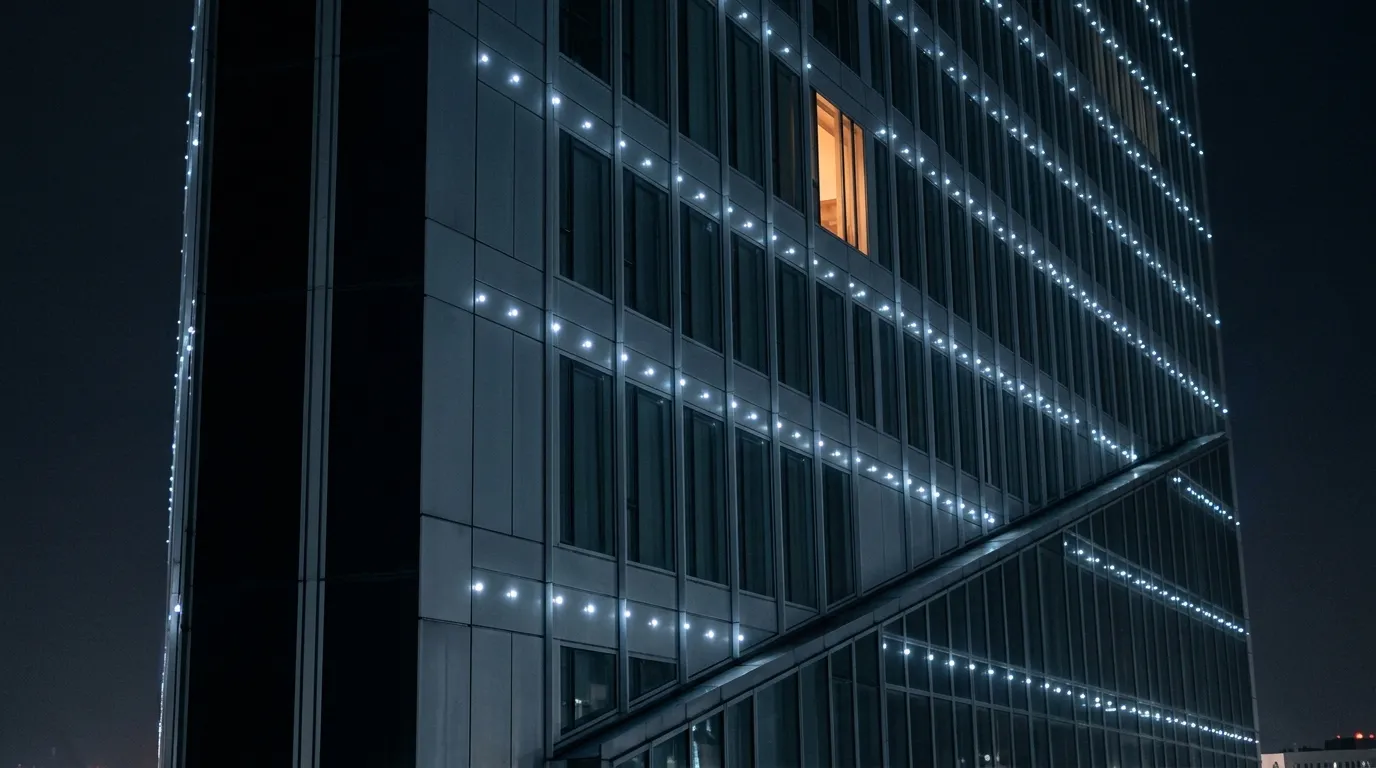
Grid alignment is the difference between an array and an accident: pitch divided into the panel module, an edge zone that is drawn and not discovered, and a placement tolerance expressed against the pitch.
Punched panel or mullion clip?
The mount is decided by the enclosure, and it determines most of the field risk. Two families cover nearly every facade:
Punched panel | Mullion clip | |
|---|---|---|
Node mounting | Node seated in a drilled/punched hole through the panel or a sub-frame | Node clipped or bracketed to the mullion, proud of the glass |
Visual result | Node sits in the plane of the cladding; reading is closest to a screen | Nodes stand off the facade; strong side views, visible hardware |
Water path | Every hole is a penetration — gasket, sealant and drainage all matter | No penetration; the facade's own weather seal is untouched |
Tolerance | Hole position is fixed at fabrication; retrofit is expensive | Clips can be adjusted on site |
Replacement | Node usually needs front or rear access to the panel | Node is reachable from the same side it is mounted |
Retrofit | Effectively a panel re-order | Addable to an existing facade |
The IP rating belongs in this decision, not in a separate conversation. IP65, IP66, IP67 and IP68 describe protection against water under progressively harsher conditions, and the rating of the node is not the rating of the assembly: a sealed node in an unsealed hole, or a node with a moulded tail entering a junction box that is not rated, is an unsealed installation with a sealed label on it. On a punched-panel grid the practical rule is that the water strategy is the panel's, and the node has to be selected to match it — which for outdoor applications in exposed locations usually means IP67 or IP68 nodes and a sealed connection behind every one of them.
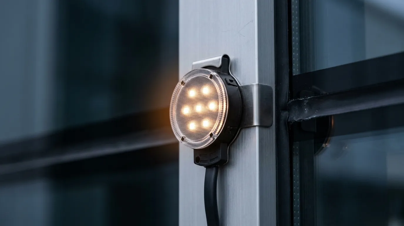
The clip route leaves the facade's weather seal untouched, which is why it is the pragmatic choice for retrofits and for grids that may need to be re-pitched after a mock-up.
Scale changes the calculus too. Where a grid runs to tens of thousands of nodes — 86,500 addressable points on one observation wheel — the mount and the wiring method stop being details and become the schedule: pre-assembled, pre-tested sub-assemblies, and a replacement path for a single node that does not require disturbing its neighbours.
Addressing, part one: how many nodes fit in a DMX universe
Specifying DMX point lights starts with a fixed number that has not changed since 1986: a DMX512 universe is 512 channels, each carrying a value from 0 to 255, sent down a single EIA-485 differential pair at 250 kbit/s (DMX512).
Divide by the channels each node consumes:
- RGB node — 3 channels. 512 ÷ 3 = 170.67, so 170 nodes per universe, with 2 channels left over and unusable.
- RGBW node — 4 channels. 512 ÷ 4 = 128 nodes per universe, exactly.
- Single-colour or dimmer-only node — 1 channel. 512 nodes per universe.
That is the arithmetic behind the "row" in the spacing table above, and it is the number to write on the drawing first. Two consequences follow immediately.
Refresh rate is bought with unused channels. A full 512-channel packet takes about 23 ms to transmit — 512 channels × 11 bits each (start, 8 data, 2 stop) is 5,632 bits at 250 kbit/s = 22.5 ms — which caps a full universe at roughly 44 Hz. If your grid only needs 120 nodes per universe, you are sending fewer channels and can run faster; if you insist on filling every universe to 170 nodes, you have accepted the slowest refresh the universe can do. For a media facade playing video, 40 Hz is adequate; for anything chasing music or strobe effects, it is not.
One controller port is one universe. A 3,200-node facade is not a big data problem and not a small one — it is exactly 19 universes at RGB, or 25 with RGBW. That is 19 or 25 controller outputs, which is why facade installations at any real scale run an Ethernet backbone and put nodes close to the load: Art-Net carries up to 32,768 universes of DMX512 over UDP (port 6454) on standard network cabling, and ANSI E1.31 — Streaming ACN, or sACN — carries up to 65,536 (Art-Net; Architecture for Control Networks). Which of the two to run is a control-system decision with its own trade-offs; for capacity planning, either one removes the universe ceiling entirely, and what limits you becomes ports, cable runs and refresh.
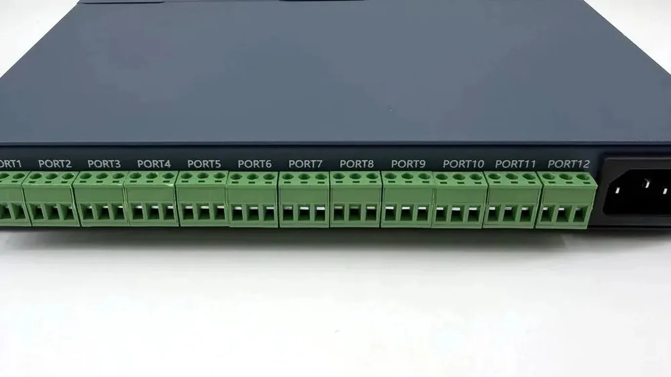
One row of output terminals is one row of universes. Twelve ports is twelve universes — 2,040 RGB nodes — and the mapping order between port number and physical node is the thing that has to be written down.
The physical layer sets its own boundary. DMX512 rides on EIA-485, a multi-drop bus specified for at least 32 unit loads with 120 Ω termination at the end of the run, extended with repeaters (EIA-485). In practice that is a limit on how many DMX devices you chain, not how many nodes you drive — a decoder or SPI driver downstream of the DMX line handles the nodes — but it is the reason facade control is distributed into racks and decoders rather than looped from device to device across a building.
Two disciplines from the Art-Net specification are worth carrying into the drawing. Addressing on the network side is typically fixed per node, often locked to MAC address and set by jumper or configuration, so a controller's identity is a commissioning task, not a runtime discovery. And the mapping order — which physical node is universe 1, channel 1 — must be written down somewhere other than the programmer's memory. A facade grid is almost never addressed in reading order left to right; it is addressed in the order the data happens to snake through the fixture string, and the mapping software is what reconciles the two. The controller capacity calculator runs the same universe and node arithmetic for a given port count if you want to check a layout before ordering controllers.
Addressing, part two: SPI puts 24 bits on one wire
Not every facade is DMX. Where nodes are dense, cheap and close together, the industry uses SPI — the same serial protocol family as WS2811, WS2812B, UCS1903 and their relatives — in which the controller shifts data down one wire and every node latches its own slice.
The bandwidth arithmetic here is sharper than DMX's, and it is the real cap on grid size. Taking the WS2812B datasheet numbers: data is sent at 800 kbit/s, and each node consumes 24 bits — 8 per colour channel. That is 800,000 ÷ 24 = 33,333 nodes per second on a single data line. Divide by the frame rate you need:
Frame rate | Nodes per data line |
|---|---|
25 fps | 1,333 |
30 fps | 1,111 |
50 fps | 667 |
60 fps | 556 |
The datasheet puts its own floor under that: at 30 fps the cascade is at least 1,024 points, which matches the calculation above. So the useful planning figure is roughly 1,100 nodes per data line at 30 fps — and unlike a DMX universe, this is not a protocol limit you can route around, it is the wire.
The same datasheet gives two more numbers that shape a facade layout. A reset code of at least 50 µs separates one frame from the next, and the signal can run about 5 m between nodes without any added circuitry — beyond that the data line needs re-driving, which is why facade wiring is star-shaped from distributed controllers rather than one heroic chain across a building. Node count per line and metres of cable per line are two separate ceilings, and a grid can hit the second long before the first.
Put the two halves together and the addressing budget for the worked example below falls out. A 3,200-node grid needs 19 DMX universes or 3 SPI data lines at 30 fps. A 28,800-node grid needs 170 universes — or 26 SPI lines. Neither is wrong; the choice belongs to the driver-IC and control architecture, which is a decision with its own comparison of colour depth, per-node cost, protocol ecosystem and voltage class, and that comparison lives in the addressable LED driver IC guide.
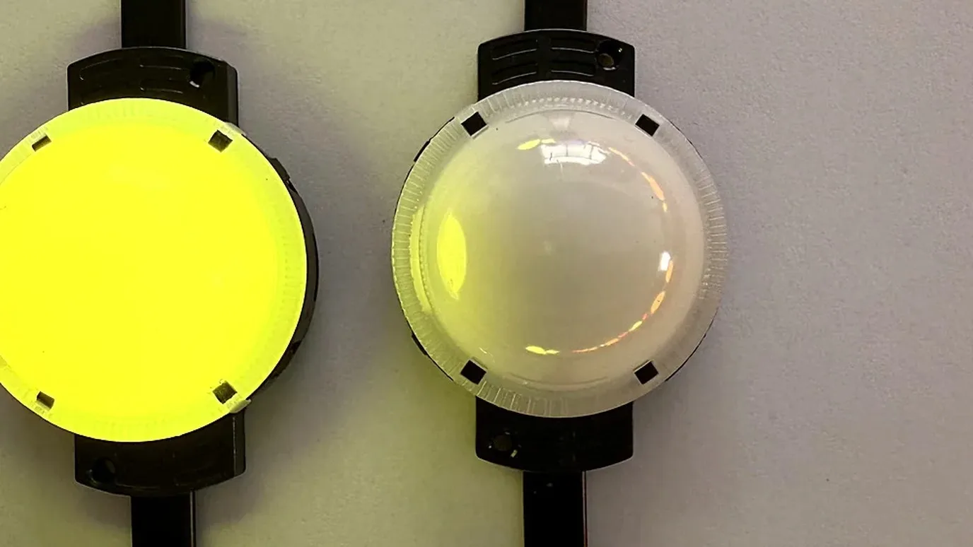
The node string is where the data budget becomes physical: nodes in series on one data line, each consuming 24 bits per frame, and a cable run that has to stay inside the re-drive distance.
Worked example: a 24 × 12 m facade section
Take a 24 m wide, 12 m high curtain wall zone and run both layers of the method through it. Two pitches, everything else constant, node rated 1.68 W at full white, RGB nodes at 3 channels.
300 mm grid | 100 mm grid | |
|---|---|---|
Nodes | 80 × 40 = 3,200 | 240 × 120 = 28,800 |
DMX universes (RGB / RGBW) | 19 / 25 | 170 / 225 |
SPI data lines at 30 fps | 3 | 26 |
Full-white load | 5,376 W | 48,384 W |
Current at 24 V | 224 A | 2,016 A |
Load density | 18.7 W/m² | 168 W/m² |
Illustrative calculation, not a product rating. Every figure above is arithmetic from the node's rated consumption and the protocol capacities in this article. The load and current columns are 100 % full white, continuous values — the worst case the content can ask for and the case the electrical package has to be sized for; real shows average well below them. Replace the node rating with your own fixture's full-white figure and the load columns change; the structure does not.
The jump between the two columns is the argument of this article in one row. The grid is nine times denser, and every downstream quantity — universes, data lines, amps, power supplies, distribution cabinets, commissioning hours — moves by roughly an order of magnitude. There is no control system that makes a 2,016 A facade easy; there is only a spacing decision that avoids needing one.
Where the power zones fall
Three thousand two hundred nodes at 1.68 W is 5.4 kW, and low-voltage DC at that scale is a zoning problem before it is a power-supply problem. The good news is that the zone map is already drawn: the injection points follow the data runs, because both want to be short and both want a cabinet at the same access point. Splitting the 24 m elevation into four 6 m columns fed from their own cabinets turns a 224 A problem into four 56 A problems, and each one is inside the range a standard distribution and cable run can serve.
That zoning arithmetic — injection spacing, feeder gauge, fuse sizing, where the cabinets live — is worked end to end in curtain wall power layout and injection points, and it is the part of a facade package where the electrical budget is actually decided. The one thing to carry back into the grid design is this: at 24 V, doubling the node count per zone means doubling the current, and the practical response is usually to go up a voltage class rather than thicken copper everywhere.
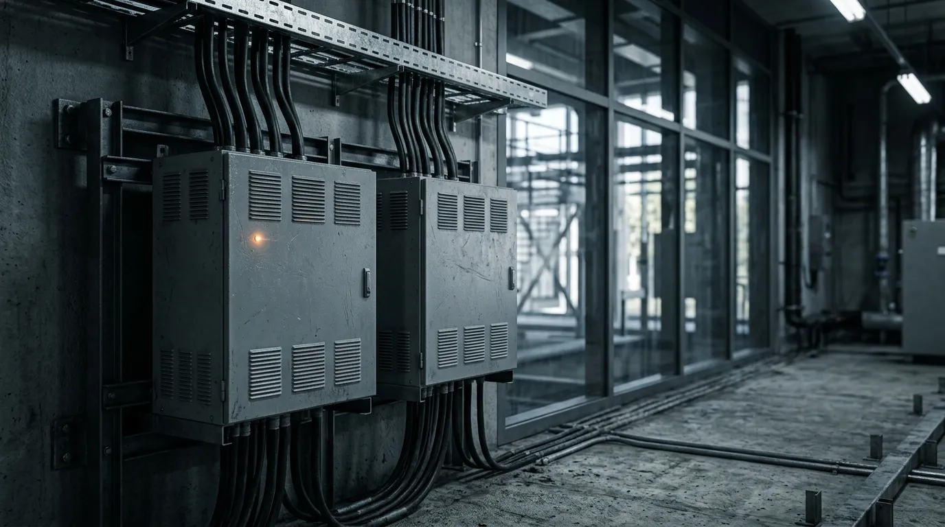
Two of the supplies for one elevation. Four zones, four supplies, four injection points — and the zone map is a drawing decision made on paper, because retrofitting zones onto a finished curtain wall is a scaffold-and-junction-box project.
The zoning above is a capacity calculation, not an installation instruction. Cabinet selection, incoming protection, earthing and the mains-side work belong to the licensed electrical contractor, and the drawings that leave this stage should say so explicitly — this article sizes the zones and the budget, nothing further.
What a point-light facade hides until commissioning
Every point-light facade looks correct in the render and slightly different on site. Four failure modes account for most of the gap, and all four are specification problems rather than installation accidents.
Colour variation across the grid. Nodes are binned at the factory, and a bin drift between production batches shows up as a visible band across an otherwise uniform surface — the single most common complaint on a media facade, and the reason per-batch colour measurement matters more here than in almost any other lighting product. Ask what is measured and how it is recorded, not whether the nodes match.
A dead node in an inaccessible place. At 11 nodes per square metre a 300 mm grid has 3,200 chances for a single point to fail, and each one is visible at night from 100 m. Serviceability is a design decision: nodes should be replaceable individually, from a side the building gives you, without disturbing neighbours, and the project should carry spares from the same production batch.
An address map that no longer matches the building. Between the render and the site, node order changes: a string is cut shorter, a section is rotated, a controller is re-patched. Nothing fails loudly — the show plays, just mirrored, or with one column shifted. The defence is a commissioning record that maps every universe and channel to a physical location, and a test pattern that makes errors obvious: full-screen colour sweeps, single-column tests, a numbered walkthrough.
Water where the panel was punched. The node may be IP68 and the installation may still leak, because the water path is the hole, the gasket, the tail and the connector, in that order. This is the failure that arrives in the second season, not on opening night.
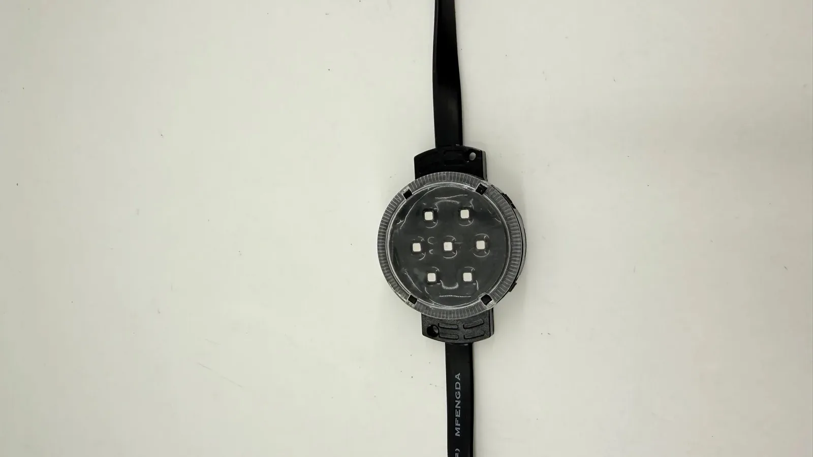
A punched node is a hole in the weather envelope with a light in it. The sealed body is only one link in the chain — the gasket at the bezel, the moulded tail and the connector behind it each decide whether that hole survives ten winters.
There is also an honest expectation to set about the light source itself. LEDs do not fail outright; they fade, and the industry measures the fade rather than the failure. L70 — the hours until output falls to 70 % of initial — is the standard useful-life statement, based on LM-80 testing (a minimum 6,000 hours, with 10,000 preferred) and TM-21 extrapolation from that test data (lumen maintenance). A decade of nightly operation at 8 hours a night is roughly 29,000 hours, which is inside the range where L70 matters and inside the range where a facade's brightness target should be set against the maintained figure rather than the day-one figure. Run the same arithmetic against duty cycle before promising a client that year ten will look like year one. The pre-power-on commissioning checklist covers the site-side tests that catch the rest before the lift leaves.
The parameter sheet to send with the elevation
Spacing and addressing cannot be quoted without a node specification, and the specification is a short list. The LED point light source is the line item the rest of the grid is built on, and these are the dimensions on which the candidates actually differ — with the forms we build at PILEDS as concrete examples of each:
Form | Node size | LEDs | Voltage | Control | IP / full-white |
|---|---|---|---|---|---|
Coin | 50 mm | 7 | DC24 V | SPI / DMX | IP67 / 1.68 W |
Half-ball RGBW | 50 mm | 7 × SMD3535 | — | DMX512 | IP68 / 1.68 W |
Globe, 360° | 80 mm | RGBIC | — | — | IP65 / — |
Pineapple, 360° 3D | 25 mm | SMD3535RGB | — | SPI / DMX | IP20–65 / 400 lm |
Aluminium body | 100 mm | 6 | DC24 V | DMX | IP20–68 / 9 W |
Square node | 12 mm | F8 RGBIC | DC12 V | WS2811 / UCS1903 | — / 0.3 W |
Eaves RGBW | 30 mm | RGBW | DC48 V | — | IP67 / 1.92 W |
A dash means the field is not stated in the model's published key specifications — fill it from the datasheet you are quoting against, and add the two numbers that decide the grid rather than the node: the node's full-white current (which sets the zone size) and its per-node address/data cost (3 or 4 DMX channels, or 24 bits on SPI, which sets the universe or data-line count). The full range — 12 mm to 100 mm, coin, half-ball, globe, pineapple and ring forms, DC5–48 V, IP20–68, SPI or DMX — is in the LED point light range.
Common questions about point lights
What are point lights? A single addressable light node — one lens, one driver chip, one address — used in arrays for facade dot grids and media facades. In this article's sense they are pixel nodes, not garden fixtures.
What are the three types of LED lights? That question belongs to general lighting, where the useful split is bulbs, fixtures and panels. On a facade the split that matters is by node form — coin, ball and globe — because the form decides the mounting method and the viewing angle more than any electrical difference does.
What is the downside of LED lights? For a facade grid, four real ones: colour varies between production batches unless it is measured per batch; output fades rather than failing, so useful life is an L70 statement, not a lifespan; a dense grid multiplies cost, load and failure points by the square of the density; and every node needs an address, which is a commissionable cost most project budgets forget.
What is pinpoint lighting? Not a term used in facade pixel specification, and not something this article covers. If you searched for it, you are probably looking for a general accent-lighting concept rather than an addressable node grid.
What to put on the drawing
Five lines turn a design intent into something a supplier can quote and a contractor can build:
- Pitch and the viewing distance it was chosen for — the pair, not the pitch alone.
- Node count and the module it aligns to — including the edge zone and the placement tolerance.
- Universe count or data-line count, with the node's channel cost stated.
- Power zone map — how many nodes per zone, at what voltage, fed from where.
- Address map ownership — who produces the universe/channel-to-location record, and when it is verified.
Those five lines are also the fastest way to find out whether a supplier has done this before: the ones who have will ask for the viewing distance before they quote a price, and will tell you how many nodes fit in a universe before they tell you about the fixture. Send the elevation and the numbers to our engineers for a layout review and we will check the spacing, the universe budget and the zone map against the building — reply within 8 business hours.
Specifying pixel LED for a real project?
Send the spec — pitch, IC, IP class, run length, voltage — and you get an engineer's answer, not a catalogue. Samples and OEM/ODM quotes from the Shenzhen factory floor.