
Powering DC48V Long-Run Pixel Strip
Powering a DC48V long-run pixel strip: what to lock down before you commit — current per meter, injection order, data limits, the 48 V boundary, site tests.
48 V moves where the risk sits — it does not remove it
Search this topic and you will meet one confident sentence in a lot of places: at 48 V DC, a long pixel run goes 30 to 100 meters with few or no injection points, so the distance problem is solved. It is the sentence sitting in the AI answer above this result page, and it is not exactly wrong. It is missing its conditions.
The reason 48 V helps is arithmetic, and only arithmetic. Power is voltage times current, so for the same wattage a 48 V run draws a quarter of the current a 12 V run draws, and half of a 24 V one. Less current through copper of the same size means less of the supply voltage is spent getting to the far end.
What that does not do is make the run risk-free. It moves the bottleneck. A feeder cable you would have fought over at 12 V becomes comfortable at 48 V, and the resistance that decides whether your far end holds its color is more likely to sit inside the strip itself — in the PCB copper that carries power along the tape — or at the joints, the taps and the connectors you add to reach the end. Data travels alongside all of it and does not get the same benefit. And 48 V DC lands you right on top of a voltage boundary with rules attached to it, which is the part almost nobody writes about.
If you are still deciding between voltage classes rather than designing a DC48V run, start with choosing the voltage class — the trade-offs are covered there and are not repeated here. And if you are lighting one room with a five-meter strip, most of this is heavier than you need — but Step 6 on sealing and Step 7 on the pre-power-on measurements still apply, and those are the two that cost people their evenings.
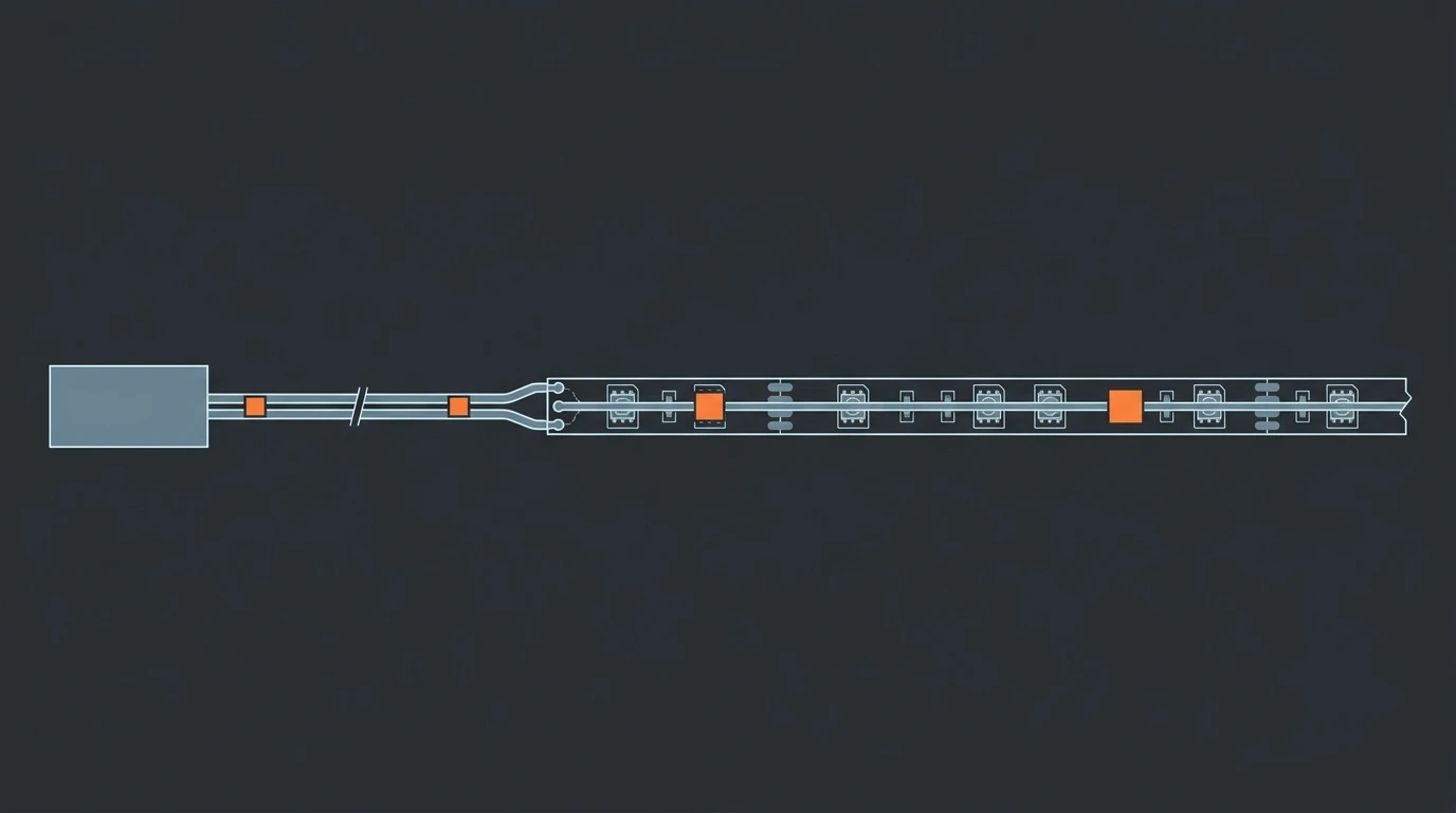
Four things sit in series between the supply and the last pixel. At 48 V the first one stops being the problem, and the last three become the things you specify.
Step 1: Turn the run into one number — current per meter at 48 V
Every decision further down needs the same input: how many amps your run carries. That is one division, and it is the only calculation you have to do yourself.
Amps per meter = watts per meter ÷ 48. Multiply by length and you have the current for the whole run.
The DC48V long-run strip Pileds builds is a useful worked case because it is dense — 90 LEDs per meter at 21.6 W/m — so it draws 0.45 A per meter. Fifty meters of it from a single feed is 22.5 A. That is the number that decides your cable, your connector choice and how many feeds you need.
Strip power density | Current per meter | 10 m run | 25 m run | 50 m run |
|---|---|---|---|---|
7.2 W/m (cove, ambient) | 0.15 A/m | 1.5 A | 3.8 A | 7.5 A |
14.4 W/m (typical feature run) | 0.30 A/m | 3.0 A | 7.5 A | 15.0 A |
21.6 W/m (90 LED/m pixel strip) | 0.45 A/m | 4.5 A | 11.3 A | 22.5 A |
30 W/m (high-output signage) | 0.63 A/m | 6.3 A | 15.6 A | 31.3 A |
Two things about reading that table. First, take the W/m figure from the strip's own datasheet rather than working it out from the pixel count — the datasheet figure already includes the driver losses that a per-pixel multiplication misses. Second, treat the rule of thumb that circulates in the hobbyist scene with care: it multiplies the number of pixels by 0.06 to get amps, and 0.06 is simply the Adafruit NeoPixel powering notes worst case of 60 mA per pixel at full white expressed in amps — their general rule of thumb is the lower figure of 20 mA per pixel. Both are 5 V numbers. At 48 V the useful unit is amps per meter, not amps per pixel, because 48 V pixel strips are built as constant-current designs in which the IC regulates current through a longer chain of LEDs.
The current is also what makes the temperature note matter. Copper resistance rises with temperature: across the standard copper tables, 12 AWG goes from 1.62 to 1.87 Ω per 1,000 ft between 25 °C and 65 °C, roughly a 15% increase (Copper Wire — Electrical Resistance vs. Gauge). A run sized cold and then sealed inside a lit aluminum profile is sized 15% optimistic. Measure and calculate warm if the strip shares its channel with anything else.
Step 2: Decide how far one feed can go before you add a second one
Three variables decide the answer, and this is where the 30-to-100-meters sentence skips its work.
The strip's own bus resistance, in ohms per meter per conductor. On a pixel strip that conductor is PCB copper, not wire — thinner than a cable, shared with the data traces, and usually the largest single resistance in the run. Ask for it in writing.
The current the run carries, from Step 1.
The input tolerance of the pixel driver ICs — how far below 48 V a pixel keeps working, and at what point the color shifts before it stops working at all.
The general form of the calculation is Ohm's law applied twice, once for the current path out and once for the return path; the voltage drop arithmetic in full works it through step by step. What I would put on a drawing is not a single number of meters. It is an acceptance criterion: the far-end voltage at the worst point of the run, and the tolerance you are willing to accept there.
Color is the sensitive one. A few percent of drop shows up as a visible gradient on a white run long before it shows up as a pixel failing to switch. That is why a specifier's version of "how long can one feed go" has an answer that says at what brightness and to what tolerance, and why it differs from the answer a catalogue gives.
Note the implication of the three variables. The same strip can have one single-feed length in theory and a shorter one in practice, because every joint and tap between the supply and the last pixel adds resistance that no datasheet figure accounts for. This is also why a run that measures correctly on a bench, in one piece, behaves differently once it has been cut, joined and closed up inside a profile.
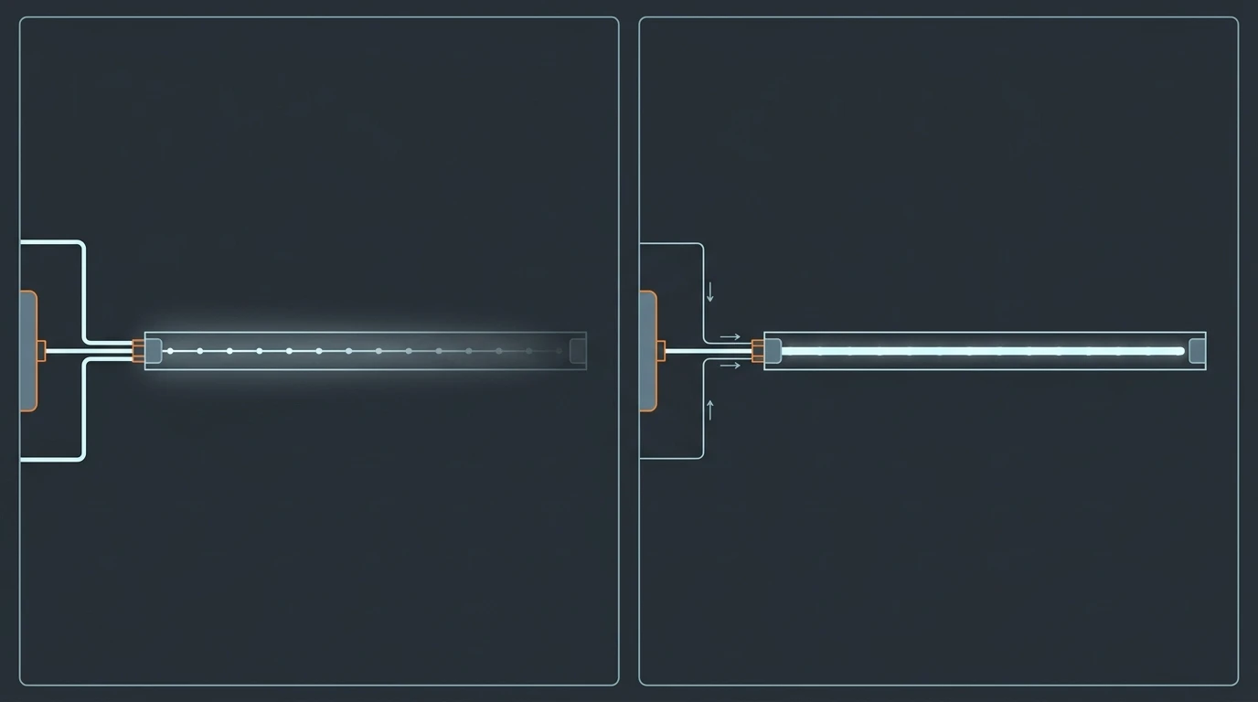
Two runs of the same length and the same load. The difference is which part of the path is the resistance — and only the second one holds its color to the end.
Step 3: Add injection points in the right order when you do need them
When the numbers say one feed will not hold color to the end, add feeds in this order. Each step roughly halves the worst-case distance between a feed and the point furthest from any feed, and each step costs more than the one before it.
- Both ends. Run a second pair of conductors back to the same supply and feed the far end. Cheapest step there is, and it removes the tail-end gradient that is easiest to see.
- Both ends plus the center. The worst-case point is now a quarter of the way along from each end.
- Evenly spaced taps, with the spacing set by the same far-end criterion you wrote down in Step 2.
Two constraints apply at every tap, and they are the ones that get missed because they are not about voltage at all.
A tap is a joint, and joints have a current limit. The working figures used across the addressable-LED scene are a maximum of about 4 A through an injection made at the end of a strip and about 8 A through one made mid-strip, with no more than 10% voltage drop allowed along the injection wire itself, as set out in the Ultimate LED Strip Power Injection Guide. Those are community conventions rather than a standard, but they exist because the failure mode at a tap is mechanical and thermal rather than electrical: a soldered pad, a push connector or a crimp carrying more current than its contact area supports gets warm, and a warm joint inside a sealed outdoor run is how a long installation fails in its second year rather than its first week.
Feeds share the current; they do not share the data. Every extra tap adds another parallel path for power. The data line stays a single series chain down the whole run, which is the next step, and it is the constraint that usually decides the real layout.
Once you are past two or three taps, the question stops being how many taps and becomes how many supplies, and how the run is divided between them. That arithmetic — including the controller port budget and where to split a big run — sets how many supplies the run needs.
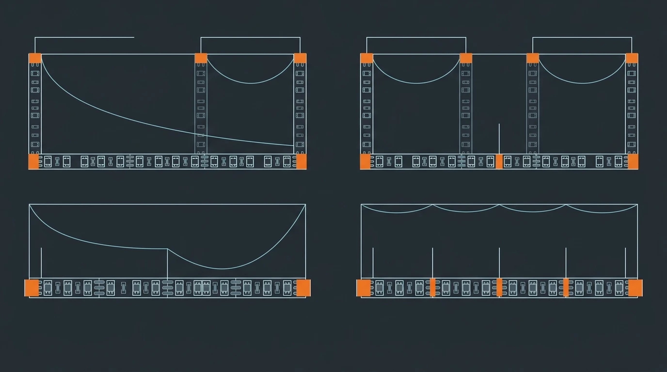
Each step halves the worst-case distance from a feed. The number of taps is a decision you make in this order, not an average pulled from a forum.
Step 4: Treat the data line as a second, shorter run
Here is the mismatch that catches people on long pixel runs. On the 50 m, 22.5 A case from Step 1 the power side is the half you have already designed for, and the data chain is the half nobody has sized yet — the serial signal each pixel passes to the next can give up long before the voltage does.
The two are different circuits with different physics. Power is a parallel network: every tap you add creates another path, and current divides between them. Data is a single series chain, and on SPI-class pixel ICs — the WS2811 family and its relatives — it runs in the high hundreds of kHz, which is distance-sensitive enough that in our own installations a run typically needs a signal booster every 5 to 10 m. DMX512 and Art-Net were built for long cable runs over proper cabling with buffered outputs, which is why long pixel installations tend to move to a DMX or Art-Net backbone instead of extending SPI indefinitely; DMX512 vs Art-Net covers how to choose between them.
Two consequences for the layout, both of which are cheap now and expensive later:
Budget the booster or the protocol change at the same time as the power distribution. Retrofitting a data repeater into a run that is already cut, joined and closed is a far bigger job than drawing it into the first version.
Ground reference matters more as the run gets longer. The data line needs a common reference to the supply feeding the pixels it controls. On a single-supply run this is invisible. On a long run with several supplies it is where "it worked on the bench and flickers on site" usually lives, because the signal now has two different references to reconcile.
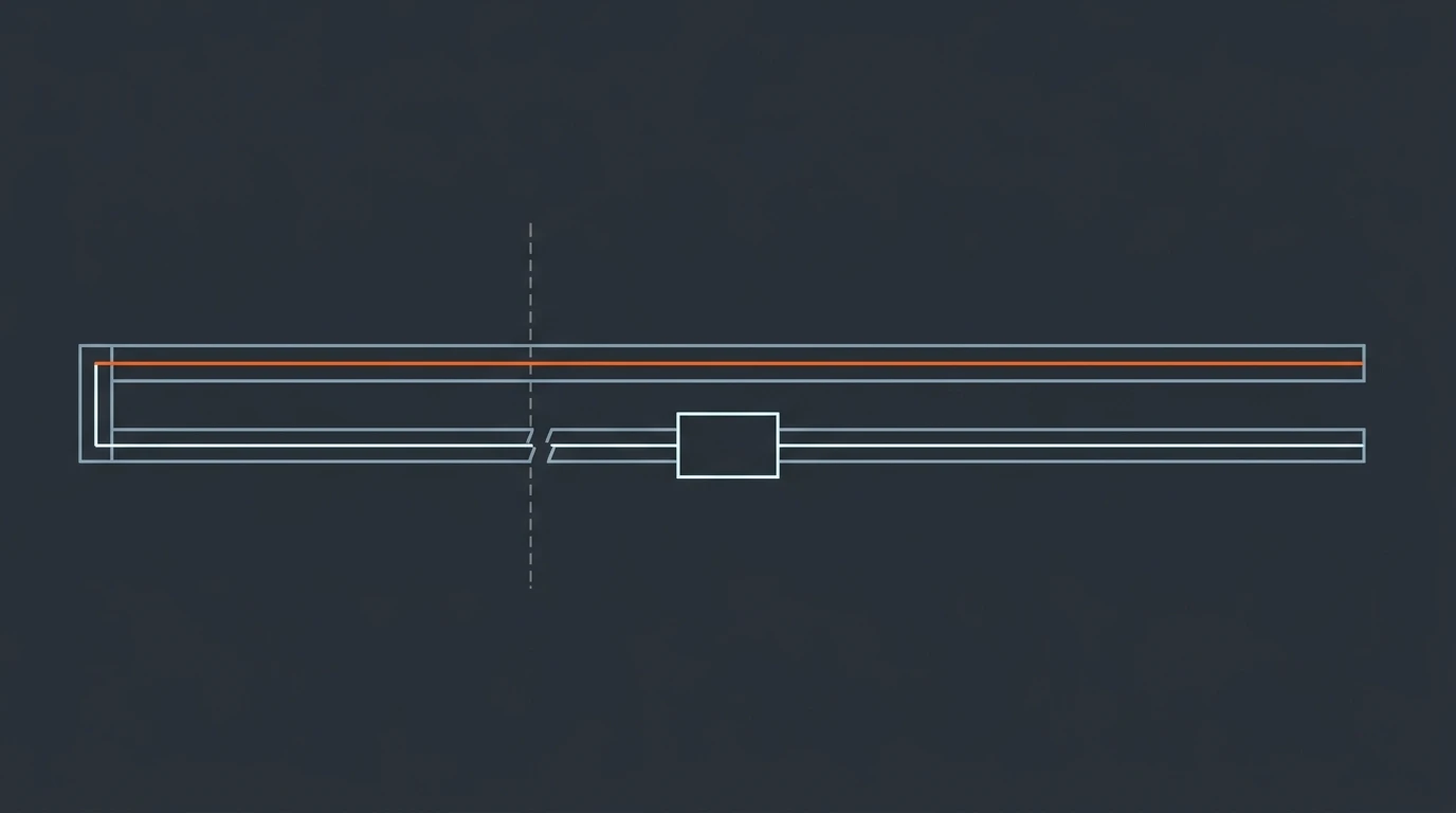
Same run, two reach limits. Power keeps going; the data chain breaks and needs a repeater — which is why the layout is decided by the shorter of the two.
Step 5: Check where 48 V DC sits against the extra-low-voltage boundary
This is the section that technical guides skip, and it is the one a specifier is most likely to be asked about by whoever signs off the electrical design.
Extra-low voltage is a defined term rather than a marketing phrase. Under IEC 61140, an ELV circuit is one whose potential between two conductors, or between a conductor and earth, does not exceed 50 V AC RMS or 120 V DC ripple-free. IEC 60364-4-41 uses the same bands, as set out in the extra-low voltage definitions.
48 V DC sits inside that band, and that buys real things. The circuit is touchable under normal conditions. It does not attract the separation and fault-protection rules that apply to mains wiring. And a side effect worth knowing: 48 V DC is also below the lower limit of the EU Low Voltage Directive 2014/35/EU, which begins at 50 V AC and 75 V DC, so a 48 V installation is outside that directive's scope.
48 V DC removes a whole class of electrical rules. It does not remove the need to know where the boundary is, because the margin between 48 V and the wet-location figure is only about 12 volts.
What the band does not buy you is margin.
The same definitions note that in more arduous conditions — wet, conductive, or otherwise higher-hazard locations — a lower band of 25 V AC RMS or 60 V DC is specified to reduce the hazard further. At 48 V you are inside 60 V with a workable gap, and it is worth keeping that gap deliberately rather than assuming it:
- Ripple and tolerance count. The 120 V figure is specifically ripple-free DC. A supply's output tolerance, its no-load voltage and any AC ripple on its output all eat into the distance between 48 V and the boundary. Specify the supply's output window rather than only its nominal voltage.
- Never stack supplies in series to reach a longer run. Two 48 V supplies in series is 96 V DC, and every statement above stops applying.
- SELV needs separation; PELV is what you have if you earth it. A safety extra-low voltage circuit must be separated from earth and from other circuits. If your design earths the DC negative — and many LED supplies do internally — you have a PELV arrangement, which is still extra-low voltage and perfectly normal, but it is a different thing to write on a drawing.
- Keep the DC side and any mains side physically separate, and leave mains-side protection where it belongs, upstream of the supply.
Two more items belong on the same list. Protect the feed at its source. A 48 V DC short is more than capable of destroying the connector it happens in, and the device best placed to stop it is the one at the supply. And have the electrical design reviewed by whoever is qualified to do so where the project sits — the framing above is the IEC one, and a North American reviewer will ask a different question first: whether the supply carries a Class 2 or LPS listing. That is a test applied to the supply rather than to the voltage, and it is worth putting to your supplier as its own line item rather than assuming the 48 V figure settles it.
None of this is exotic. It is the difference between "48 V is safe" as a slogan and the specific reasons the band is drawn where it is drawn.
Step 6: Specify sealing as a system property, not a strip rating
An IP rating on a strip tells you what happens to that strip. It tells you nothing about the run, because the run is not the strip. The run is the strip plus every cut end, every joint, every injection tap, every cable entry and every connector.
This is where long-run and short-run installations diverge most in cost. A three-meter indoor strip has one connection and therefore one place to get wrong. A 60 m outdoor run at 48 V has dozens, and they are the parts you cannot inspect once the fascia is closed.
Practical consequences:
Match the connector to the location, not the strip rating. An IP65 strip in a dry location with well-made joints is a better specification than an IP68 strip with one unprotected tap. The IP grades do not form a simple hierarchy — a higher number is not automatically the right answer in a given location — so establish what each grade actually survives before you choose a connector to match it.
A cut end is an opening. A strip rated as a sealed unit is rated as a sealed unit until you cut it. Every cut needs a defined termination method, not an assumption.
Seal at the entry, and let water out rather than in. Glands and junction boxes should be oriented so that moisture which does get in can drain away. A fully potted connector that traps water against a warm joint is worse than one that vents.
A tap that carries current must also be sealed for that current. Sealing is not a separate problem from Step 3; it is the same joint, seen from the other side. If a tap is marginal thermally, no amount of potting fixes it.
The components that decide all of this — connectors, glands, end caps, profiles, injection leads — are the part of the bill of materials people leave until last, and the part that makes a run cheaper or more expensive than it looked on paper. They get their own guide: connectors, profiles and injection leads.
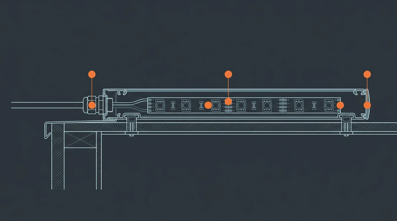
Four openings rather than one. The strip's own rating covers none of them, because none of them exist until the strip is installed.
Step 7: Write the pre-power-on measurements into the program
The most useful single thing you can add to a long-run program is a measurement gate before the strip is powered for the first time. Not because the design is likely to be wrong, but because a handful of readings turn "something is off" into a specific fault in five minutes instead of an evening.
Do the unpowered checks first. With the strip disconnected they cannot damage anything.
What you measure | Instrument | Pass criterion |
|---|---|---|
Supply output, no load | Multimeter, DC volts | Inside the supply's specified output window; record the no-load figure, it always sits above nominal |
Polarity at every tap | Multimeter, continuity | Positive and negative match the drawing at every tap and at the controller |
Insulation resistance across the field wiring, supply and strip disconnected | Insulation tester | No leakage path; a reading here is a pinch or a wet joint |
Far-end voltage at 0 / 50 / 100% brightness | Multimeter, DC volts, under load | Stays above the pixel IC's minimum input at full white, and the drop across the run is inside the figure you wrote in Step 2 |
Voltage at each injection tap, under load | Multimeter, DC volts | Taps within a few tenths of a volt of each other; a tap reading low is a bad joint, not a supply problem |
That insulation reading only means something with the supply and the strip disconnected. On a PELV arrangement — the negative bonded to earth by design — an in-place test will read continuous on a perfectly correct installation, so isolate first, or test the positive rail against earth instead.
Measuring at three brightness levels is the part people skip. The strip's load scales with brightness, so its drop does too; a run that looks perfect at dimmed output is exactly where the far-end sag appears first when you push it to full white. A working version of this list, with the order and the record sheet, is on the pre-power-on commissioning checklist.
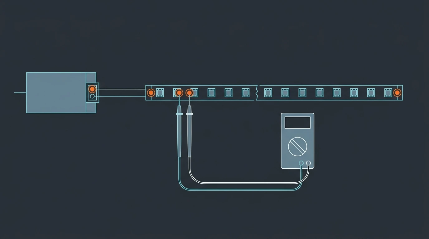
Three readings and one instrument tell you whether the run matches the drawing before the first pixel is lit. Program them as a gate, not an afterthought.
Is it power or is it data? An isolation order for the first fault
When a long pixel run misbehaves, the instinct is to blame the supply. Often the data line is responsible instead, and the two present differently enough to separate in a couple of measurements.
What you see | First test | What it usually is |
|---|---|---|
Everything dim, uniformly | Supply output under load | Supply sizing, or a supply fault |
Bright at the feed, fading toward the far end | Far-end voltage under load | Power — drop you have not accounted for |
Correct up to a point, then dark or frozen | Data at the last working pixel | Data — the signal chain, not the voltage |
Wrong colors from one point onward, correct before it | Data continuity and ground reference | Data direction, or a broken ground reference |
Random flicker, worse at high brightness | Ground reference between supplies; tap temperatures | Grounding, or marginal joints |
Order matters. Check voltage first because it is one measurement and eliminates half the tree. A dim far end with everything else healthy is a power problem nine times out of ten; the tenth is a symptom worth understanding rather than guessing at, and the field procedure for that case is in diagnosing a dim far end on site.
When the run should be a custom quote instead of a stock order
Long DC48V runs are where stock ordering stops being the right model, and it is worth knowing the line before you buy rather than after.
Work through it in this order: the length of the longest unbroken run, the power density in W/m, the number of feeds that implies, the IP rating the location demands, and the protocol the controller speaks. If a run needs more than two injection points, a non-standard length, a connector that does not exist off the shelf, or an IP rating assembled to order, you have already passed what a stock SKU handles. Specifying it properly at that point is cheaper than discovering it on site.
The parameters to put in front of a supplier are short, and every one of them comes out of the steps above — run length, W/m, voltage, IP rating, protocol, number of feeds, and the far-end voltage you are prepared to accept. Send those and the reply is a fixture specified against them, rather than a reel that arrives with the hard part still undecided. The project RFQ and BOM template has the fields if you would rather build the list first, and our engineers can work from it directly: we build DC48V long-run pixel strip, including the 90 LED/m, 21.6 W/m family used as the worked example in Step 1, together with the controllers, decoders and address writers that drive it. Send the run and its constraints through the contact page and you will get a quote back for the fixture matched to your voltage, length and protocol.
Specifying pixel LED for a real project?
Send the spec — pitch, IC, IP class, run length, voltage — and you get an engineer's answer, not a catalogue. Samples and OEM/ODM quotes from the Shenzhen factory floor.