
Rehearsal Checklist for Pixel Fixtures
A rehearsal checklist for pixel fixtures: binning and colour checks, DMX addressing and universe planning, voltage drop along the run, data-line tests, spares.
A rehearsal checklist for pixel fixtures covers six domains, and all six are cheaper to test now than on the night: colour and binning consistency, DMX addressing and universe planning, power and voltage drop along the run, the data line and controller, spares and failure cover, and handover to the lighting crew. Most pre-show lighting checklists stop at "power everything up and see if it lights" — a test that says little about an addressable rig, because the failures that ruin a show are rarely total: the one bar on a run that sits two shades off, the universe that runs out eleven pixels before the end of the truss, or the far end of a power run that sags to orange at full white. Each of the checks below is written as a pass condition you can point at, so the answer to "is the rig ready?" stops being an opinion. This is the sequence PILEDS hands to rental houses and integrators before a rig goes up.
The order matters. Addressing cannot be verified once a rig is in the air, power and data faults mimic each other, and a spare that has never been addressed is not a spare. Work top to bottom: the result is a pixel fixture setup checklist for the ninety minutes before doors, ending with the paperwork that lets someone else run your rig without you.
What a pixel fixture rehearsal has to prove
A pixel rig fails in three ways, and the checks that catch them are different.
Colour failures are slow and quiet. A fixture from a different production batch can sit visibly off the rest of a run — and on camera, under a shutter with white balance locked, a mismatch the eye accepted turns obvious.
Control failures are structural. An address conflict, a run that exceeds a universe, a controller with a firmware version older than the rest of the rack: none of these announce themselves until the content asks for a channel that does not exist.
Power failures are physical and variable: a run that passes at 30 % browns out at full white, and the failure point moves with load, temperature and how well the connectors seated that day.
A generic touring lighting checklist does not catch any of the three: all of them live inside the pixel layer, the part of the rig where 170 points share one universe and one power run. The fixture questions underneath it — which bar, which tube, which IP rating, which driver IC — belong in the stage and touring pixel LED guide; this article starts after the fixtures are in the case.
A checklist is not there to prove the rig works. It is there to prove you know what happens when it does not.
Colour and binning checks: prove the fixtures match before they go on the truss
LED binning is the sorting step at the LED reel. Every diode is measured and dropped into a bin by luminous flux (brightness) and by dominant wavelength (colour) — the reason two "identical" pixel bars from two production runs can look different on the same fade. The same idea has an objective language: ΔE, the distance between two measured colours in a uniform colour space, where a bigger number means a bigger visible difference (colour difference / ΔE). You do not need a spectrophotometer — a dark room, a solid field, and the same fixture types side by side will do. The colour system the fixtures run — RGB, RGBW, RGBIC — also decides how many channels each pixel occupies and how white gets mixed, and it is worth settling before anything is addressed (RGB vs RGBW vs RGBIC).
Run it in this order:
- Lay the run out flat, side by side, in the order it will hang. Any fixture that is out of step shows up faster lying on the floor than on a truss.
- Drive a full-field 100 % white and walk the run. Look for fixtures that read warmer, cooler, greener, or simply dimmer than their neighbours — this is the white everyone sees at the top of a cue.
- Drive pure red, then green, then blue, one at a time. Single-colour fields expose what white hides: a red-shifted fixture often matches on green and blue.
- Scan for dead and stuck pixels at each of the four fields. A pixel that never lights is dead; one that stays on a single colour when it should be off is stuck, and it draws attention every time the content goes dark. Note the exact pixel count from the start of the run, not "somewhere in bar 7" — that number is what a replacement gets addressed against.
- Check the low end of the dimming curve. Take the run from 0 to about 10 % output and watch for pixels that snap on late, flicker, or jump a step ahead of the rest. Low-end behaviour is a fixture-and-controller pairing issue, and it is invisible at show levels.
- Repeat under the camera you will actually shoot with. A camera does not integrate light the way your eye does: a rig that is stable to the eye can band or crawl on a short shutter. Test with the real camera and shutter angle; if bands appear, the fix is the refresh rate or the fixture's position in frame.
- Compare batches, not just fixtures. If the tour carries two shipments of the same bar, run them against each other — this is where bin mismatch actually bites.
- Write the result down. A short table of "run, fixture ID, batch, passed white / R / G / B" is what turns a colour argument at 2 a.m. into a replacement decision.
If a batch does not match, group the odd fixtures into their own run rather than spreading them across the rig — keep them out of any group that has to hold white together. When reordering, ask for the bin code on the reels — the lighting team can see the batch story from a spec sheet, and a manufacturer that measures colour per batch can tell you whether the next shipment will match the last.
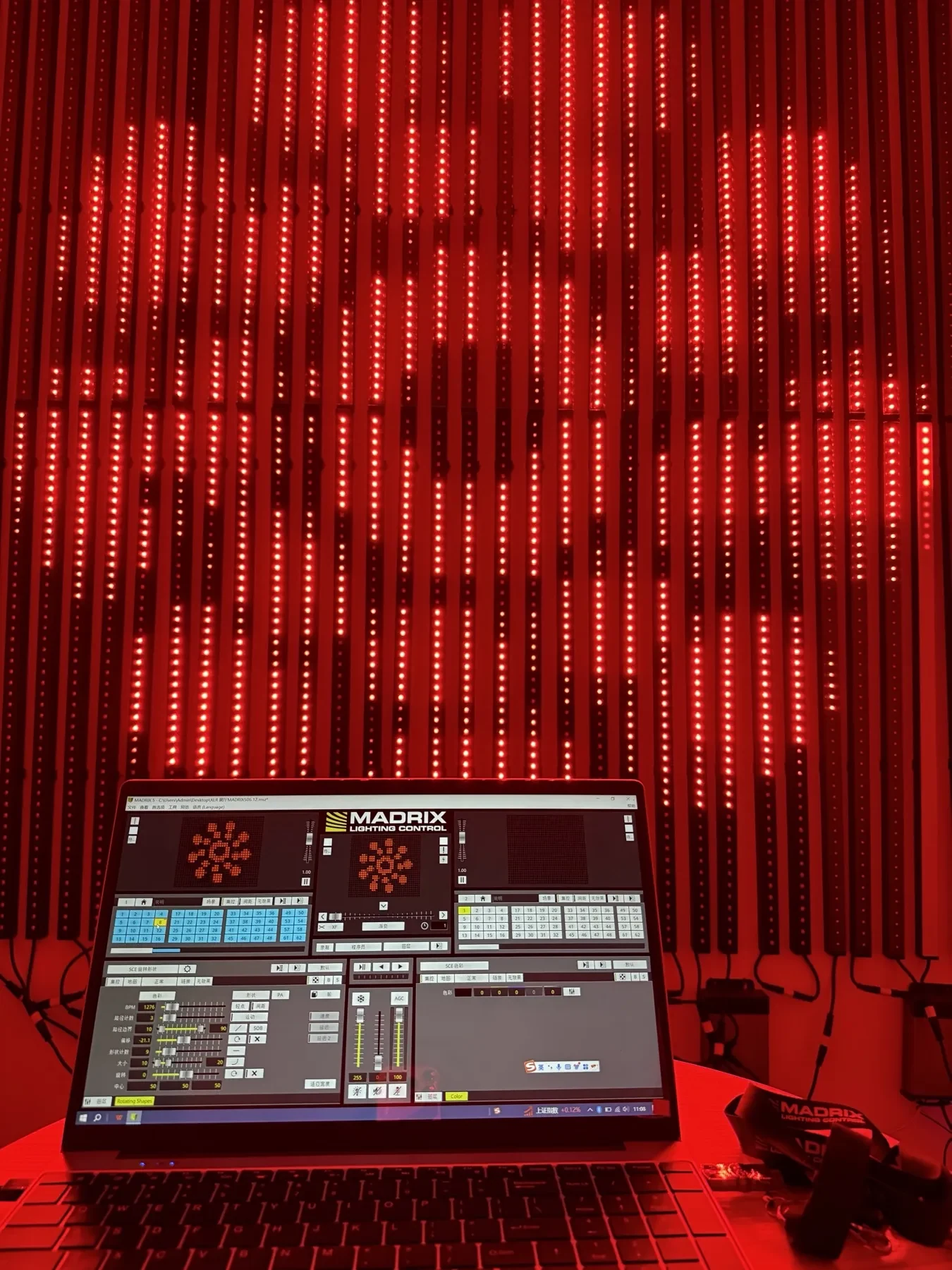
A solid single-colour field is the cheapest test in this article: one colour across the whole wall makes a fixture that is out of step almost impossible to miss.
DMX addressing and universe planning: build the patch before you plug in
Addressing is arithmetic, and DMX universe planning is the part of a pixel show that fails silently. A DMX universe carries 512 control channels — that is what ANSI E1.11 defines, alongside RDM (ANSI E1.20) for remote device management and sACN (ANSI E1.31) for the network transport, all three listed in the ESTA published document index. Pixels eat those channels three or four at a time:
Control mode | Channels per pixel | Pixels that fit one 512-channel universe | Where it bites |
|---|---|---|---|
RGB | 3 | 170 | The default pixel bar, tube or node |
RGBW | 4 | 128 | White-heavy looks; 42 fewer pixels per universe than RGB |
RGB + extra attributes | 5–6 | 102 / 85 | Fixtures exposing dimmer, strobe or macro channels |
Build the patch sheet before the first fixture is addressed, and make it the same document the console and the controller see — one lighting patch sheet template, not two versions that drift. It needs: fixture ID, physical position, universe, start address, control mode, and the controller output it hangs off. At scale those budgets disappear quickly, and the DMX controller capacity calculator runs the same arithmetic if you would rather check the number than trust the sheet.
Then run the DMX addressing checklist — these are the four ways it goes wrong:
- Duplicate start addresses. Two fixtures at the same address mirror each other perfectly — which reads as "the content is wrong", not "the patch is wrong".
- Overlapping ranges. A 60-pixel RGB bar starting at channel 1 occupies 1–180. The next fixture must start at 181, not at 100. Overlaps overrun the later fixture's early pixels, so the symptom shows up on a fixture that is correctly addressed.
- Mode mismatches. A fixture left in a 4-channel mode while the patch assumes 3 shifts everything after it on that chain — the classic "the last bar on the run is doing the wrong thing".
- Universe overflow. The end of a run sitting past channel 512, chasing its tail into the next universe. Recount the last fixture on every universe, not the first.
Verify the patch physically, with a march test rather than a look: send the front of the universe to pixel 1 and add pixels one at a time, or use the controller's sequential test, confirming that each step lights the pixel you expect in the order you expect. Any fixture that responds out of order is either mis-addressed, inverted in the run, or patched to the wrong output. If the fixtures support RDM, use the identify or blink command to find a specific fixture without moving, and change its address from the console instead of carrying a ladder — but do not rely on RDM across a wireless hop or a long chain, where discovery is what fails first.
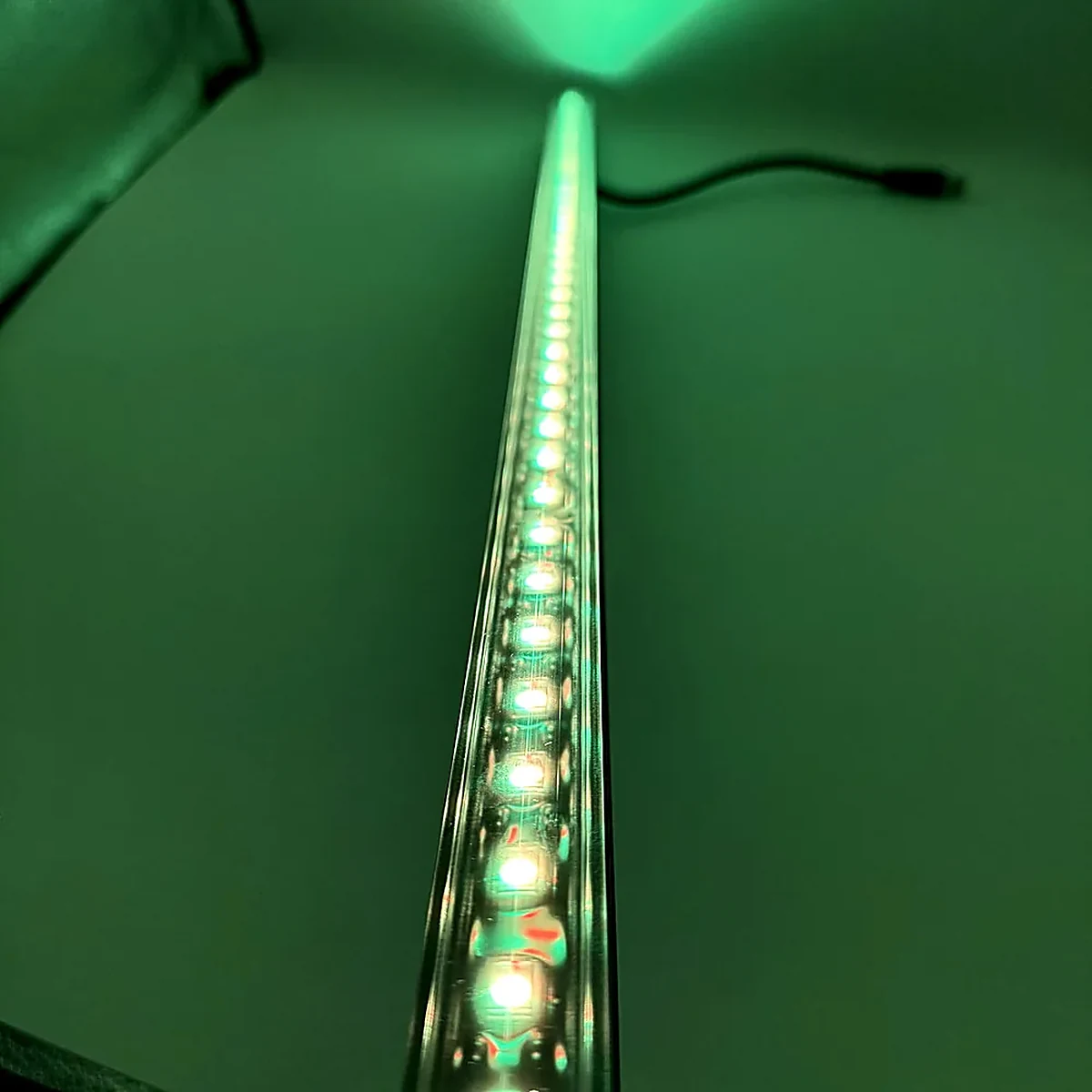
Every point inside this bar holds an address. The march test walks them one at a time so the patch sheet and the rig end up agreeing on which one is which.
Finish by labelling: every fixture gets its patch ID on a tape flag, and every cable gets a number at both ends. The rehearsal is the last moment when labelling is cheap.
Power checks: measure the voltage drop along the run, not at the PSU
A pixel run is a long resistor with LEDs hanging off it. Current travels out through the copper and back through it, so the voltage at the far end is always lower than at the supply, and the loss grows with current, length and conductor resistance (voltage drop). The visible result is the voltage drop LED strip symptom everyone reports: bright and neutral at the supply end, dim and colour-shifted at the far end — the complaint behind "the pixels at the end of my run won't hold white", and the reason 24 V and 48 V fixtures exist for long runs: for the same wattage, doubling the voltage halves the current, and the percentage drop falls faster still. Which voltage suits a given run is a spec decision made earlier and belongs with the 12 V vs 24 V vs 48 V comparison; the rehearsal measures what the installation actually produced.
- Measure at the far end, under load, at full white. A meter at the supply proves the supply; a meter at the last fixture proves the run. Take the reading with the run off and on the highest-load cue — that gap is the drop you are budgeting for.
- Take the same reading at each injection point, and confirm the far end of every run sits above the fixture's floor — where the drop is the limiting factor, the voltage-drop and injection calculator solves for where the injection points belong.
- Compare the far end against the fixture's minimum operating voltage, not the nominal figure. A run that ends slightly under nominal is usually fine; one that ends under the fixture's floor behaves unpredictably at low output long before it visibly fails.
- Check the return path. Injection points only help if the return leg is as short as the feed — injection into a single-ended run with a long return is a common half-fix.
- Confirm the supply, breaker, cable and connectors are rated for the load you measured, not the load you planned on paper.
- Seat every mains connector and re-check it. Locking mains connectors (powerCON-style and TRUE1-style) and their cheap equivalents fail at the joint far more often than at the PSU. Pull-test each one, then re-measure after the rig has been struck and re-hung.
- Check the power-up order. Bringing a whole rack up on one switch can trip the breaker on inrush before any fixture has done anything wrong; stage the power-up in groups and confirm nothing browns out mid-boot.
- Listen for hum and look for flicker that has nothing to do with content. A ground potential difference between the pixel system and the audio or video system shows up as hum, or as pixels twitching when another department switches something on. Fix the reference, not the fixture.
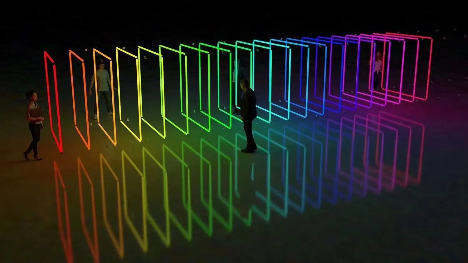
The further a run spreads, the further the last fixture sits from the supply — which is why the far-end measurement is taken under load, at full white.
Venue mains work — new outlets, breaker changes, fixed wiring — belongs to the venue's electrician. The rehearsal checklist verifies what is there; it does not rewire it.
Data line and controller checks: Art-Net, termination and failover
The data side has a hard budget too, and most Art-Net setup problems turn out to be physical rather than logical. Copper Ethernet is good for about 100 m per segment before a switch or fibre takes over; Art-Net is royalty-free and defined to address a theoretical limit of 32,768 universes on one network, per the Art-Net specification. A touring data line is usually a mix of the two worlds — Ethernet from the console or media server into an Art-Net node, then DMX or SPI from that node out to the fixtures — so check each hop for what it is.
- Walk the whole chain with the show running, not a static look. Trigger one universe at a time and confirm every fixture on it responds; a run sharing a universe with another must not stutter while that one moves.
- Check the run lengths. Every copper segment inside the limit, every long span on fibre or behind a switch, every cable labelled at both ends — a fault that only appears at full rig size is usually a length or a bad crimp, not the controller.
- Terminate DMX lines properly and keep the chain a chain. DMX is designed as a daisy chain with termination at the far end (DMX512 structure and practice); a star wired by hand, a splitter used as a repeater, or an unterminated long line produces dropouts that move when you move a cable.
- Check the switch, if there is one. Keep the lighting VLAN separate from video and control traffic and configure multicast handling, or a node can flood the network. Note which port the node is on — the first cable to reseat.
- Confirm the addressing behaviour of the controller (Art-Net controller and decoder range): which output maps to which universe, whether it uses unicast or broadcast, and what it does when two sources hit the same universe. If the rig merges a backup console, verify that merge deliberately, not during a takeover.
- Check the refresh rate against the content and the camera. A long run at high pixel density is a bandwidth problem; if the frame rate drops, the symptom is tearing, judder or a visible scan across a fast pan.
- Run the rig with the source disconnected. Many controllers play an SD-card show without a console — the cheapest insurance on the tour, but only if it has been tested with the current show file and patch.
- Record the firmware version on every controller and node. A mixed-firmware rack behaves differently output to output, and you cannot diagnose that by looking at the rig.
- Test the failure case on purpose. Pull the primary data cable, or kill the console, and watch what the rig does: whatever it does then is what it will do on the night, and the crew should know before the audience does.
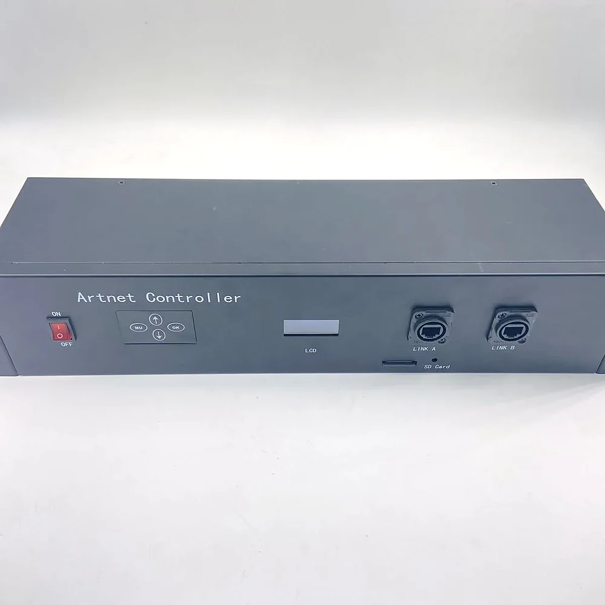
A node with two network ports, a front-panel display and a card slot is where the failover path, the output mapping and the standalone show file all live.
The rehearsal-day test sequence: T-90, T-30, T-0
Sequencing is what makes the checks above executable rather than aspirational — the times are indicative, the order is not.
When | Check | Pass condition |
|---|---|---|
T-90 min | Colour and binning scan on the floor, before the rig flies | Every fixture matches its neighbours on white, red, green and blue; dead and stuck pixels logged by channel count |
T-60 min | Addressing and patch verification, march test, labelling | Every fixture answers at the address on the patch sheet, in sequence, with no duplicates or overlaps |
T-45 min | Power: far-end measurement at full white on every run | Far end above the fixture's floor, drop inside budget, every mains connector pull-tested |
T-30 min | Data line, controller and merge behaviour; console-connected run-through | No dropouts on any universe with the show playing at speed; merge and failover behave as documented |
T-15 min | Content run-through on the actual cues — the cue-to-cue with sound, not a static look | The cues that use the pixel rig play start to finish with no addressing or timing surprises |
T-0 | Standby with spares staged, positions marked, crew briefed | Everyone knows the spare location and the first thing to swap |
The T-15 line is the one that gets skipped. A static look proves the rig lights; a cue-to-cue proves it does the show, including the transitions where two departments touch the same moment.
The first two lines overlap with pre-power-on commissioning, which gates the same interfaces before the first test. In this article's terms: nothing is driven at full output until the addressing and the data path are proven at low level, one universe at a time.
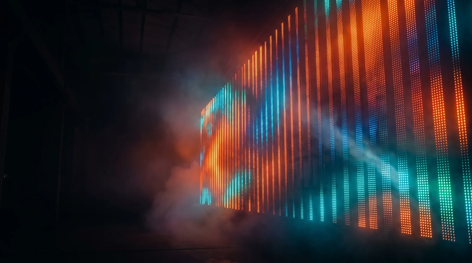
Playing the actual cues end to end is what catches the addressing and timing problems a static look never surfaces.
Failure modes and spares: what goes on the truck
Failure cover starts with triage — the same order any pixel bar troubleshooting should follow. Establish: is it the fixture, the address, the data line, or the power run? Swapping a fixture before you have checked the address is the most common wasted ten minutes on a tour — an unaddressed replacement looks exactly like a dead one.
- Stage the spares already addressed. A spare pixel bar should arrive with the patch ID, mode and address of the position it is most likely to replace, or at least with an address writer and a printed patch sheet next to it.
- Size the kit off the worst single point of failure, not an average. One spare per fixture type per run, a spare output's worth of spare cable, and a power supply that matches the largest single run means any one failure is a swap rather than a re-plan. The supplies in the kit follow the same maths.
- Match the spare to the batch, not just the model. A replacement DMX pixel bar from the same production batch is worth more on the truck than a newer one that will not sit next to its neighbours on white.
- Carry the small parts that stop a swap. Locking mains connectors, spare data couplers, a terminator, spare fuses, tape and a label printer. Those are what turn a repair into a replacement.
- Swap in one move. Power off the run, not the rig; mark the position; unplug both ends; replace; re-run the march test on that run only.
- Keep an offline path. Carry the current show file on a card in the rack — it is the only spare that covers a dead console.
- Brief the crew on what not to touch. On a pixel rig the difference between a data fault and a power fault is usually one cable — the cable someone is most tempted to reseat at full power.
Handing over to the lighting team
At some point you stop being the person who built the rig and become the person the tour calls. Hand over four things, in writing, and the rig survives that transition.
- The patch sheet, current as built. The lighting patch sheet template the console is patched from, updated to what was actually addressed — not the version that was designed.
- A universe and power map. Which controller output feeds which universe, which run is on which supply and breaker, where the injection points are and where the far end sits. This is the sheet that saves the next load-in.
- The known-issues list. Any fixture with a dead pixel, any run near its voltage floor, any universe near its channel ceiling, and the firmware versions in use. A documented weakness is manageable; an undocumented one is a surprise.
- A sign-off. The lighting designer or the venue's technical contact confirms the rig performs as specified — the same conversation as rental check-in, and much shorter with a rehearsal record attached. It is not bureaucracy: the 600 m launch-stage pixel bar delivery we shipped to India went through the same handover.

The end state the whole checklist is for: a rig someone else can run, in a venue you have already left.
Rehearsal checklist for pixel fixtures: FAQ
How many pixel fixtures fit in one DMX universe? 512 channels per universe, three channels per RGB pixel — so 170 pixels. RGBW pixels use four channels, giving 128 per universe. Any fixture that adds attributes takes more.
How do I calculate a fixture's DMX address? Start address of the previous fixture plus its channel count. A 60-pixel RGBW bar occupies 240 channels, so the next fixture starts 240 channels later. Build the chain this way on a patch sheet before touching a fixture.
Can you run DMX over Cat5e or Cat6? Yes — DMX over a twisted pair with the correct pinout travels well inside the same distance limits as any copper run, and Cat cable survives a touring rig better than light microphone cable. What does not work is treating an Ethernet run as a DMX daisy chain: the two need different wiring and different termination.
What voltage drop is acceptable on a pixel run? Rather than a fixed number, compare the measured far-end voltage under full white against the fixture's minimum operating voltage, and keep the drop consistent across runs so none visibly lags the others.
How many devices can you daisy chain on one DMX line? The practical limits are 32 devices per line and roughly 300–400 m before a repeater (published figures vary); pixel loads consume more of that budget than conventional fixtures, so count loads, not just fixtures.
Do I need an artnet node, or can the console drive the pixels directly? An Art-Net node (often written artnet node) converts the network universes back into DMX or SPI where the fixtures live. A console with direct network output still needs that conversion at the rig, so node count belongs in the universe plan.
Does the same checklist work for a permanent install? The domains are identical; the truck kit becomes a documented maintenance interval plus a stored patch and show file.
If the rehearsal turns up fixtures that will not hold colour together, or a run that runs out of channels before it runs out of truss, the fix is usually a closer look at what was specified: which fixture type suits the position, and which driver IC is inside it. Pixel bars vs pixel tubes covers that comparison, and if you are replacing a run or adding universes before the next leg, send us the spec and we will check the numbers against the same list.
Specifying pixel LED for a real project?
Send the spec — pitch, IC, IP class, run length, voltage — and you get an engineer's answer, not a catalogue. Samples and OEM/ODM quotes from the Shenzhen factory floor.